regulator circuit logic question

Thread Starter

yef smith

Joined Aug 2, 2020
1,446
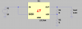
Hello,In the photo shown bellow I have a circuit.
This circuit is only an example .
In page 11 we have a much simpler implemetation of tuning output shown in the link.
Two questions:
What is the logic of this trimmer and the capacitor attached to it?
Its suppose to supply 3A at most to the output,How can we be sure that I_adj=3uA?
We can output 1A 2A 3A how can we be sure I_adj will remain 3uA?
Thanks.

https://www.analog.com/media/en/technical-documentation/data-sheets/1764fb.pdf
1755691854633.png
1755691875512.png
 

panic mode

Joined Oct 10, 2011
4,864
capacitors before and after regulator are used to stabilize it (prevent oscillations).
some regulators are adjustable. this means output can be set by external components. potentiometer is that component. it allows you to set output voltage.

actually the adjustable regulators are also fixed... their output does not change but it is lower than usual. (typically 1.25V or 1.5V). and that would be the case if ADJ pin was tied to GND. but it is not...
so R2 is used to create small load current (usually 10mA or so).

then this current is also sent through R1 to GND. by changing R1 value, you get to control the output voltage.

to be really precise, current through R1 is sum of two currents:
a) current through R2 (the "big" current of 10mA or so)
b) current out of the ADJ pin (the "small" current, usually something like 0.05mA or less). in most cases this is small enough that it can be ignored.

for example, this regulator output is 1.21V. so if we want 10mA through R2, R2-1.2V/0.01A = 120 Ohm.
and if total output voltage is 5V, we need this 1.21V (across R2), PLUS additional 3.79V (across R1).
so R1 = 3.79 V / 0.01A = 379 Ohm.

1755692421636.png
 

dl324

Joined Mar 30, 2015
18,219
What is the logic of this trimmer and the capacitor attached to it?
The trimmer sets the output voltage by controlling the adjust current. That current should be chosen to be at least 10 times the quiescent current (max, not typical) out of the ADJ terminal.

The capacitor is to stabilize the voltage at the ADJ terminal. 22uF seems rather large.
We can output 1A 2A 3A how can we be sure I_adj will remain 3uA?
The quiescent current out of the ADJ terminal is designed to remain relatively constant. By making the adjust current much larger than the quiescent current, the effects of it varying are minimized.
 

panic mode

Joined Oct 10, 2011
4,864
do the math... Iadj is tiny 3uA or 0.003mA
when this is much smaller than Ibias, Iadj can be ignored.
which is why i suggested 10mA for Ibias (as a rule of thumb)
and 10mA is much bigger than 0.003mA

using R2 = 120 Ohm and R1 = 379 Ohm we get

Vout = 1.21*(1 + 379/120) + 0.000003A * 120 Ohm
Vout = 5.03158V + 0.00036V = 5.03194 V
you can see that contribution of Iadj is only 0.00036V and much less than 5.03158V so it can be ignored.
when you choose large R2 value, this may not be ignored. (other example used 4.1k here)

1755693893230.png
 
Last edited:

crutschow

Joined Mar 14, 2008
38,316
10mA through R1 and R2 is larger than needed.
The LT1764 regulation values are spec'd with a minimum output current of 1mA, thus the values of R1 and R2 can be selected so that at least 1mA flows through them at the desired output voltage, which is achieved if R1 is no larger then 1.2V / 1mA = 1.2kΩ.
Iadj will then still have very little effect on the selected output voltage.
 

Thread Starter

yef smith

Joined Aug 2, 2020
1,446
Hello,my goal is to supply to many amplifiers in parralel 5V ,totally all the amplifiers consume 0.6A current.
Vref=1.21V
given the simulation shown below is I_ref is always the same Iref=3uA?
I have I_bias and I_load,How do I design them in my situation?
 

Attachments

Last edited:

drjohsmith

Joined Dec 13, 2021
1,549
Hello,my goal is to supply to many amplifiers in parralel 5V ,totally all the amplifiers consume 0.6A current.
Vref=1.21V
given the simulation shown below is I_ref is always the same Iref=3uA?
I have I_bias and I_load,How do I design them in my situation?
a little background on these three pin regulators,

they are an analog circuit,
Iadj is a "leekage" current that comes out of the adj pin.
Vadj pin is a high impedance input.

the resistors r2 and r1 make a divider of the output voltage.
the chip works by changing the resistance between in and out, to keep the voltage at Vadj constant.

the voltage at the vadj is generated by the current through the lower resistor R1.
that current is the current out of Vadj , and the current coming through R2..

so as mentioned above , if the current through R1 is 99 percent from R2, then Vadj current is insignificant.

a big part of engineering is knowing , or quickly determining whats relevant.
 

drjohsmith

Joined Dec 13, 2021
1,549
BTW. many amplifiers , remember to put decoupling near each amplifier , and check your LDO minimum and maximum capacitance on its output.
 

Thread Starter

yef smith

Joined Aug 2, 2020
1,446
Hello,The problem Is I need to deliver 600mA to the load and my load needs to be 5V.
suppose I neglect the Iadj, I can create 5V with R2/R1=3.13V So I canhave many cmbination for achiving this.
How do I deside which resistors to put so my current on the load will be 600mA?
Thanks.

1755761354331.png
 

drjohsmith

Joined Dec 13, 2021
1,549
Hello,The problem Is I need to deliver 600mA to the load and my load needs to be 5V.
suppose I neglect the Iadj, I can create 5V with R2/R1=3.13V So I canhave many cmbination for achiving this.
How do I deside which resistors to put so my current on the load will be 600mA?
Thanks.

View attachment 354534
This is a constant voltage output regulator chip.
It changes it's resistance in to out, such that the voltage out is held constant .

If you need a constant current output , then you wire the chip differently or use a different chip , then the chip varies it's output voltage to keep the current constant .

Are you certain you need a constant current , or just ability to provide up to that amount of current ?

I'll just mention, these chips vary their resistance to keep voltage output constant.
The power dissipated in the chip is the voltage drop across the chip multiplied by the current.
I can't remember your vin and vout values , but if we assume vin of 10v and vout of 5 v, at say 500 mA, the chip dissipates 2.5 watts as heat. Ensure you can get rid of that heat .
Other things to keep in mind
They often have min and max capacitance on the output .
They have a minimum vin , and there is a minimum voltage drop across the chip. Like vin must be at least 1.5 v above vout.
It's all in the data sheets , but for such a simple 3 pin chip , you will not believe the number of times I've seen then used wrong
 

Thread Starter

yef smith

Joined Aug 2, 2020
1,446
Hello , My question Is I can choose R1=10K R2=3K and I can choose R1=100K R2=30K
It will be give the same Vout, What will be the difference between both options?
 

drjohsmith

Joined Dec 13, 2021
1,549
Hello , My question Is I can choose R1=10K R2=3K and I can choose R1=100K R2=30K
It will be give the same Vout, What will be the difference between both options?
The resistors just set the v out .
As you have seen, there is a leekage from Vadj, of sat a few uA. Check data sheet
si to all intent and purpose , the voltshe out is set just by the resistor ratio of R1 r2. The actual values don't matter provided the current through them is around 10 times the leakage .
We tend to use standard value resistors , and try to minimise the different values on one board.
 

Thread Starter

yef smith

Joined Aug 2, 2020
1,446
Hello Eric, what is the intuition for choosing the R1 R2 values? I see that the Biasing currnent is tottly different.
I need to supply my amplifiers with current (at most 600mA) and I need to supply them with 5V
So my regulator is a current or voltage source?
If its a voltage source becasue it has to keep 5V no matter the current then I need to have low output impedance on this regulator so the voltage will fall on the amplifiers?
Or should I consider the regulator as a current source?
Thanks.


hi yef,
Check this LTS sim.
E
View attachment 354537


1755775721647.png1755775745023.png
 

Thread Starter

yef smith

Joined Aug 2, 2020
1,446
Hello , so If its a voltage source we need to have high output impedance so the amplifiers (low input impedance)
Will have all the 5V.
So given the simulation below I can use R1=10K R2=3K and I can use 10 time larger values or 100 times larger values which will make the same ratio.
What is the intuition regarding choosing the proper resistor ratio?
Thanks.
1755778443816.png
 

dl324

Joined Mar 30, 2015
18,219
So given the simulation below I can use R1=10K R2=3K and I can use 10 time larger values or 100 times larger values which will make the same ratio.
What is the intuition regarding choosing the proper resistor ratio?
You want the current in R1 to be at least 10X the worst case current out of the ADJ pin.

If you want the regulator to regulate with no load, the current in R1 should be at least 1mA.
 
Top