Looking for help on circuit design. 5V regulator heating up (I think)

Thread Starter

cdebrebisson

Joined May 5, 2024
10
Hello,

I know enough about electronic to put myself into troubles :-( and I think that this is what I might have done.

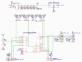
My project, use a 12V power supply for a board with an ESP32 and 3 steppers (using makerbase closed loop motors).

The 5V sub-system uses around 0.6W (0.11@5V as measured by my USB-C power monitor when I power the system using USB-C)...

My issue is that when I power the system through the 12V supply, my 78M05 regulator seems to be getting quite hot (enough to wanting to touch it!).

Can someone tell me what I am doing wrong?

Thanks,
Cyrille
 

Attachments

nsaspook

Joined Aug 27, 2009
16,249
What type of heat-sinking are you using for the regulator?
https://www.ti.com/lit/ds/symlink/lm78m05-mil.pdf

The LM78M05-MIL device is a fixed positive voltage regulators. It can accept up to 35 V at the input and regulate
it down to outputs of 5 V, 12 V, or 15 V. The device is capable of supplying up to 500 mA of output current,
although it is important to ensure an adequate amount of heat sinking to avoid exceeding thermal limits.
However, in the case of accidental overload the device has built in current limiting, thermal shutdown and safe operating area protection to prevent damage from occurring.

https://www.ti.com/lit/an/snva036b/snva036b.pdf
AN-1028 Maximum Power Enhancement Techniques for Power Packages
 

BobTPH

Joined Jun 5, 2013
11,463
The regulator is dropping 7V at .11A. That is .77W. A TO220 can handle up to 1W without a heat sink, but it will be quite hot.
 

MrChips

Joined Oct 2, 2009
34,628
You don't need all those capacitors C1-C6 on the input side, one will do.
What you do need is a 1-10 μF on the input side and another 1-10 μF on the output side of the linear voltage regulator.
 

Thread Starter

cdebrebisson

Joined May 5, 2024
10
Hello,

> The regulator is dropping 7V at .11A. That is .77W. A TO220 can handle up to 1W without a heat sink, but it will be quite hot.

But I have a TO252 package :-( No clue how much this one can support. And no heatsink of course (and since I placed the chip UNDER the ESP32 board, no room to add one!)
What would you advise as a better solution to this? I "know of" DC-DC, but I have no clue how to implement one, and even less how to design a PCB for it!. If I could find a circuit that I could copy-paste, it would be great...


> You don't need all those capacitors C1-C6 on the input side, one will do.
Actually, I think (?) that I need at least some of them as the circuit controls 3 (maybe 4) stepper motors which require them (well, in theory, one each, but I put some extra "in case of heavy load or bad supply", was that an error)

> What you do need is a 1-10 μF on the input side and another 1-10 μF on the output side of the linear voltage regulator

I assumed (incorrectly?) that the C1-C6 would happily replace the input 1-10µF capacitor, which is why I did not put it. Is that an error?
I did NOT place the output capacitor as the 5V rails enters the ESP32-Board which "starts" with decoupeling capacitors and a 3.3V regulator... I assumes (incorrectly?) that this meant that I did not need to place a cap on my side of the "equation".

Thanks for the comments!
Cyrille
 

MrChips

Joined Oct 2, 2009
34,628
You have two misconceptions.

1 μF in parallel with 100 μF is 101 μF. But 10% tolerance of the 100 μF is much greater than the smaller value. So why bother?
The reason is that the frequency response of the two capacitors are different. The lower value capacitor is better at attenuating higher frequency noise.

The physical location of power line bypass capacitor is critical. You need to locate the capacitor as close as possible at the pins of the device to avoid circuit inductance. The decoupling capacitor at the output pin of the linear voltage regulator is there not for noise reduction but to prevent the regulator from oscillating.
 

BobTPH

Joined Jun 5, 2013
11,463
But I have a TO252 package :-( No clue how much this one can support. And no heatsink of course (and since I placed the chip UNDER the ESP32 board, no room to add one!)
Is it soldered to a board? The heat sink is the copper on the board and the board itself. It should be soldered to a copper pad at least as large as the pad on the bottom of the package.

It should easily be able to handle up to 1W with any reasonable mounting.

Getting hot is not necessarily a problem, depending on how hot.

With all due respect to my more knowledgeable colleagues, I doubt that there is any circuit problem. What you are seeing is likely the inevitable heat produced by the device operating normally.
 
Last edited:

nsaspook

Joined Aug 27, 2009
16,249
Is it soldered to a board? The heat sink is the copper on the board and the board itself. It should be soldered to a copper pad at least as large as the pad on the bottom of the package.

It should easily be able to handle up to 1W with any reasonable mounting.

Getting hot is not necessarily a problem, depending on how hot.

With all due respect to my more knowledgeable colleagues, I doubt that there is any circuit problem. What you are seeing is likely the inevitable heat produced by the device operating normally.
+1

1734109982650.png
 

MisterBill2

Joined Jan 23, 2018
27,164
You are also, apparently, missing the 0.1mfd capacitors right at the 5 volt regulator. Those are to prevent instability and oscillation, and other issues. You might possibly, maybe, get by without them for a short while, maybe. OR you might have an unseen oscillation along with heating problems.
 

Thread Starter

cdebrebisson

Joined May 5, 2024
10
Hello,

I did not know, of these oscilations issues :-(
So, my design is crap :-(....

Anyhow, for the next version, due to the way too high power loss at the regulator (0.7W on battery!), I will be using a DC-DC down-regulator... But instead of designing the circuit, I have found some pre-made mini-boards on ali-Express, which are designed to be either through hole mounted, or direct soldered on the PCB... That is what I will use as they can only be better than me at power/analog design!
https://fr.aliexpress.com/item/1005006308573192.html

Thanks for all your insight and teaching me new things!
Happy holydays,
Cyrille
 

MisterBill2

Joined Jan 23, 2018
27,164
I only said that those additional capacitors, which are physically small, and cheap, were missing. No judgement on the rest of the design. THAT was the only FLAW I noticed.
 

Thread Starter

cdebrebisson

Joined May 5, 2024
10
Hello,

> I only said that those additional capacitors, which are physically small, and cheap, were missing. No judgement on the rest of the design. THAT was the only FLAW I noticed.

Sorry, I did NOT mean to imply that you said that my design was crap! or that I felt offended in any way, shape or form!!!!

When I said: "So, my design is crap :-(.... "
I meant: "I messed up the power part of the design"... Which is a pretty epic fail considering that there is only 1 component there!!!

I know enough to know that power electronics is outside of my skill set (I guess I could learn, but I don't have enough of a need to justify spending the time...
Hence the change of system for V2...

Thanks for the explanations as to why these caps were important...
Cyrille
 

Thread Starter

cdebrebisson

Joined May 5, 2024
10
Hello,

The stepper controller is actually "ON" the stepper motor, it's one of these new makerbase closed loop controler systems...
https://fr.aliexpress.com/item/1005003340856835.html

The documentation is minimal for such a complex thing, and nowhere does it specify caps or anything like that... but since it is designed to replace existing stepper drivers, which all require caps... I added the caps!

So, this aside, a broad description of the power stage of the circuit is

12V in. Bunch of 100µf cap in parallel. 12V to steppers (4 of them). 12V to 5V regulator
5V regulator to ESP32 board
On the ESP board, the 5V is transformed to 3.3V using another regulator with 3 caps at the entrance: 47µ, 22µ and 100nF... So, in essence, my 5V regulator has filtering caps on the output :)

That 3.3V is then used to drive the whole ESP32 system, AND the input signal part of the stepper (i.e: power 3 mosfets used to inverse/protect the driver CPU from the input... So I doubt that there is much there...)

So, yes, especially if the steppers cause a lot of ripple on the 12V supply, despite my 5*100µf caps (I guess they don't do much against high freq stuff)... Then it would cause oscilations on the input side of the regulator.

Cyrille
 

MisterBill2

Joined Jan 23, 2018
27,164
OK, with the steppers being fed from the 12 volt side, those capacitors are certainly appropriate, not an error!!
The small caps mounted at the regulator are what has been advised for such regulators, by the manufacturers, since their introduction, and are quite separate requirements from the other caps.
If the regulator is still dropping 7 volts, and no room for a heat sink on the 5 volt regulator, a trick would be to put an 8 volt regulator, with a heat sink, in the 12 volt feed to the 5 volt regulator. Certainly a bit "hokey", but that would reduce the heating. Of course, that 8 volt regulator will also need the 0.1mFd capacitors.
 

Thread Starter

cdebrebisson

Joined May 5, 2024
10
Hello,

I have noticed the problem after receiving the PCB V1.
So, I have to redesign the PCB anyway, and order a new set...
So I might have well update from the regulator, with it's low efficiency (0.7W loss) to a "98% efficient" DC-DC convertor... Even if not as efficient as advertize, it still will be much better battery wise :)

Cyrille
 
Top