Locking potentiometer? Recessed?

Thread Starter

james211

Joined May 29, 2012
291
Thanks for your insights RB,

Standard aquarium pumps are way too strong. The amounts that are being dosed are way too small to depend on an aquarium pump. For instance with my aquarium the amount of calcium solution dosed per/hr is roughly 2mL.

I have looked into other options such as diaphragm pumps but then you have to worry about internal parts touching and calcium build up. In the end I looked at what all companies are using for their consumer available dosers and all of them are peristaltic.

My thoughts here are this, if the user sets up their pump as it would be used and runs a series of (10-20) test runs using the exact liquid and measures they need in their tank, then measure each of those amounts and average them, they should get a pretty good idea as to how much each pump is dosing. Granted this may need to be done every 3-6 months, but that would be considered maintenance.

Also, it is important to use a high purity tygon tubing as its specifically designed for peristaltic dosers. Its more flexible and regardless it maintains it original form for quite some time.
 

THE_RB

Joined Feb 11, 2008
5,438
Ok then if settled on the DC peristaltic pumps you can run them closed loop or open loop.

Closed loop requires a RPM sensor on the motor shaft, which may or may not be available or able to be added. Closed loop then allows you to turn the motor an exact number of turns which gives an exact number of turns at the pump after the gearbox. With the high amount of gearing you can probably just count motor revolutions, there will be lot of them for one pump revolution.

If you want to go open loop then I suggest you keep the motor driver impedances very low, as this reduces the effect of load slowing the motor down. So it means more stable speed for any fixed PWM duty.

So you would need a high current regulated voltage PSU, and low resistance PWM FETs and low resistance cabling. And large schottky freewheel diodes at the motor terminals.
 

Thread Starter

james211

Joined May 29, 2012
291
Unfortunately I'm going to have to stick with open loop. My last option for a reasonably priced, geared, 12v motor just fell through. I was trying to get a hold of Welco pumps out of japan, but apparently some other aquarium doser company has exclusive rights to their pumps - I'm quite bummed about this. The other companies that I've found that make 12VDC geared pumps are very expensive, over $150/pump.

Anyway, back to your answer - Open Loop! With that in mind, I'm starting with one of these as my PWM controller. I'm expecting criticism about this, and I'm prepared - so can you offer me a better option for a PWM controller if need be?

When you say high current, how high of current? I was going to start with one of these for testing.

low resistance PWM FETs
Can you point me to one on mouser, jameco, etc please?
And large schottky freewheel diodes at the motor terminals.
Can you point me to one on mouser, jameco, etc as well please?

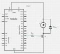
I've attached a photo of an arduino motor diagram, is that the correct way to hook up a diode? Can the diode be on the controller end rather than on the motor since the motors will never be running at the same time?

I'm sorry for asking for such details, but I really am a visual person, and seeing schematics, drawings, or actual pictures really do help me out.

Also, would it be cheaper, or better to build my own PWM controller? I also have a 12v-40v 10a PWM controller here at home, would that be better to use?
 

Attachments

Last edited:

Thread Starter

james211

Joined May 29, 2012
291
So I ordered a higher quality PWM controller today, actually I ordered two of them. I'm hoping to tear one down to reverse engineer it a bit. I ran a series of tests today with the version I have here, and just like you said, the low duty side was a bit less accurate than I liked. At medium and high speed it was quite accurate.

The new one that ordered has the following specs:
Working Voltage: DC 6V - DC 90V (Ultra wide working voltage)
Control Power: 0.01 - 1000W(Max current :15A)
Static Current: 0.005A ( Standby)
PWM Duty Cycle: 0% -100%
PWM Frequency: 15Khz
Voltage control:0-5v(Voltage -mode control ,can use PLC to control the motor speed directly)

With power reverse connection protection, has complete protection from overvoltage, 20A to quickly fuse the ceramic fuse ,can use PLC voltage to control directly
.

If this performs better I'm going to look into building my own to save some money. I received all of the pots today, both multi-turn and multi-turn trimmers, both seem to work quite well.

If I can get the low end of these motors figured out I'll be in good shape.
 

THE_RB

Joined Feb 11, 2008
5,438
You can probably order the pumps cheap from Alibaba.com. Depends on what quantitiies you can afford (MOQ).

Since you have committed to Arduino (or at least some type of micro) I would just build the PWM parts yourself. Those small DC motors which are likely to be <12v and <500mA when running.

So all you need to drive 4 DC motors are 4 decent N-channel FETs and 4 schottky diodes, and some decent sized electro caps and of course the wiring.

It will help to have a play with the DC motor pump and different PWM levels and get an idea of the voltages and currents you will be dealing with when it is running at the typical dosing speeds.

I like to run the motor from a variable DC supply with voltmeter and ammeter, to see the volats/amps at different speeds and loads. That will help a lot to determine the PWM characteristics.

For instance if the motor needs 3v DC and draws 400mA at the slow speed, then you can use 12v PSU and 25% PWM to give 3v, and the current drawn from the 12v PSU will be approx 100mA when the motor is getting 3v and 400mA.
 

THE_RB

Joined Feb 11, 2008
5,438
Your schematic from your post #23 is fine, as the TO-220 N-channel FET has the same pinout as the TO-220 transistor you showed. It needs a large cap 470uF or 1000uF across the red and black wires.

The diode should be a schottky type, 1A at least assuming the motor current is <500mA at running speeds.

We kinda need specs on the volts and amps the motor requires when running, doing the task.

If you just want general overkill I would suggest;
TO-220 N-channel FET >20A >30v
TO-220 dual schottky diode dual 10A, >20v
Cap 25v electro 470uF or 1000uF depends on size and budget

Those parts are cheap and common enough and will give a very large safety margin, and good motor sag performance due to the low impedances. You should not need heatsinks.

If you want to cut costs or use smaller sized parts we need to know the running specs, ie PSU voltage, motor volts and amps running at the worst case speeds and loads.
:)
 

Thread Starter

james211

Joined May 29, 2012
291
Great info!

Here are the PSU Specs:

  • Output Voltage (VDC) : 12
  • Output Current (A) : 1.3
  • Total Power Output-Max (W) : 15.6
  • Switching Power Supply
As far the motors goes, they are 12v, I'll do a current load test this weekend and get specs on that.

One last question, I recently read an article about using small caps, .1uF or .22uF on the motor terminals to reduce noise and interference. Especially since this project depends on a wifi controller. Would you agree with that? Would it hurt? Here is the article.
 
Last edited:

Thread Starter

james211

Joined May 29, 2012
291
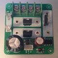
So I received two new PWM controllers in the mail today, these seem quite solid I have to say. But I need a bit of help deciphering whats what.

So right now I know it has the following:

2 - B30100G Schottky Diodes
1 - IRL2910 Power Mosfet
1 - 470uF 100v Cap
1 - 470uF 35v Cap
1 - 10.0 ohm resistor (colors are Brown Black Black Gold Brown)

Then there are three other what looks like diodes and an 8 pin chip of some sort.

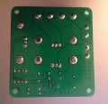
Here is a picture of the front and back. My questions about this are - why are there two schottky diodes, and whats up with the 8pin chip, resistor and extra diodes?

In the mean time, I'm working on a circuit based on what you told me earlier. Once verified, I'm hoping to get an eagle file and a sample board made some where.
http://www.aliexpress.com/store/pro...0-B30100G-High-quality/125462_1524645409.html
 

Attachments

Thread Starter

james211

Joined May 29, 2012
291
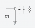
OK, so I have a first draft of a controller. I don't have the specs yet for each part as I still need to test the current draw on the motor under load. But these are the basics. What I haven't put on here, as I'm not sure if it belongs on a schematic or not, are the caps on the motor terminals. Based on a post above it looks like those will be either 0.1uF or 0.22uF caps.
Parts:
1 - TO-220 N-channel FET
1 - TO-220 dual schottky diode dual
1 - 25v 470uF or 1000uF electro cap
1 - 12v, 1.3amp PSU
1 - 10k Bourns Multi-Turn Pot
Based on what I've mentioned above, does my schematic check out? I've never done a schematic before, so any insight would be great!
 

Attachments

THE_RB

Joined Feb 11, 2008
5,438
Re the commercial PCB, the chip is driving the gate pin of the FET, so it is a FET driver. It's job is most likely to provide fast switching of the FET gate from ON to OFF etc. A chip number would help know more.

I'm not sure why they have used two schottky diodes, but the one closer to the chip seems to be across the power rails. That's not usually necessary and its likely to be some type of reverse polarity protect, maybe just to blow the fuse if PSU is reverse connected.

Your schematic is wrong, the diode is reversed. And the cap is not needed and will cause issues with the PWM. Please redraw the schematic so PSU+ is at the top, and GND at the bottom, it is more standard and easier to read.

If you want us to help fine tune your circuit to commercial level (ie you mentioned reducing noise) we need to know a lot more about your wiring type and length and what test equipment you have etc.

Fortunately the motors will likely be quite low current and will tolerate low freq PWM very well, so that can save you a lot of noise hassles. :)
 

Thread Starter

james211

Joined May 29, 2012
291
Got it! I'l work on the schematic again today.

Questions regarding the caps:
And the cap is not needed and will cause issues with the PWM.
In post #27 you mentioned I needed a Cap 25v electro 470uF or 1000uF depends on size and budget.

I'm a bit confused now...

Also, the little 8pin chips have no writing on them. Could it be on the underside? I do have quite a few different PWM controllers here and all of them see to have it.

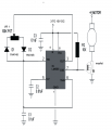
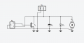
Here is another schematic I found that seems more inline with the pwm in my hands now. Also, I've attached an updated schematic, hopefully I did this one right.
 

Attachments

Last edited:

Thread Starter

james211

Joined May 29, 2012
291
So I've tried a few things today and in the end haven't really come up with an answer. I made some mistakes...good and bad.

So I found some TIP120's laying around here, so I hooked it up with one of my 10k pots. Realized very quickly I needed a resistor on my pot after a fried a few. Tried a 1k, it burned, finally got to a 2.2k and had no troubles. However, I'm not getting great PWM. Its almost an ON and OFF scenario, unless I turn the pot really really slow, but either way the range is far from what I need.

I peeled peeled off some of the B30100G Schottky Diodes from one of those PWM boards I received, that didn't seem to change much. I added a 470uF capacitor as well, same results.

When I put a volt meter on the motor at low speed, the volts range from 9.4 - 10.2v. I'm not sure where to go from here?

I also tested the newest PWM controller I purchased, this guy, and it works soooo perfectly. I tested it down to as low as 4v and the power doesn't fluctuate a bit! The motor under load draws very little. I have my meter set to 20m and the max reading I'm getting is .2 and thats at full speed, pumping liquid. When I set it at the lowest possible speed, it draws .15.
 

THE_RB

Joined Feb 11, 2008
5,438
Ahah! Seeing that last amazon photo it looks like the PWM controller uses an onboard 555 oscillator, which is the 8pin IC. It also looks to be the same (or very similar) to your earlier posted PCB?

Your schematic is still wrong! The vertical placement is like this;
+PSU (+12v etc)
motor
FET drain pin
FET sounce pin
gnd (-PSU wire)

Then the motor has the diode across it, in parallel. And the FET gate pin is driven by your 555 circuit, or by your arduino.

It's good that you are getting some actual measurements with the motor and PWM now. :)

Your meter won't read the PWM current or voltage exactly because they are pulsed, but the ball park figures you are getting (4v 0.2A) are right around where I would expect for that little DC motor running at low speed.

I think you need to make a hard decision about whether you are going to use a Arduino or 555 in your final project (product?), and if you want to buy 4 PWM modules or design your own PCB and use 4 FETs and 4 diodes which will be a lot cheaper.

Now we know your motors only require a low current the task gets cheaper and easier. :)
 

Thread Starter

james211

Joined May 29, 2012
291
Well I did a bit more research, both on this forum and another, and from all of the responses most seem to agree that I won't be able to reproduce these controllers for less than $10 unless I'm building a whole ton of them.

The PWM controller I showed you on amazon works so perfectly that I think I'm going to build my project on those. I wish they were a bit smaller is all. Right now the project uses a sparkcore as the micro controller. I tried to build the project using that plus a motor shield but the core has a max output of 3.3v and most of the motor shields need at least 5v on the MOSFET gate to work. So to keep it simple I'm using a manual PWM adjustment.

If you really think I can build this small controller board for less than $10, including having a prof PCB made, let me know and I'll continue working on this with you.

A second option is this, I have a few of these laying around, I've also attached the schematic, but it doesn't do very well at low speeds. The size is perfect though! Is there anyway to use this build and modify it to work at low speeds? I have permission from the original builder, Dale Wheat, to use it, he even gave me the eagle file.
 

Attachments

THE_RB

Joined Feb 11, 2008
5,438
Well I did a bit more research, both on this forum and another, and from all of the responses most seem to agree that I won't be able to reproduce these controllers for less than $10 unless I'm building a whole ton of them.
...
I'll disagree with that. If your product drives 4 DC motors from a microcontroller PCB (like the sparkcore) it only needs;
* a small PCB $3
* 4 FETs $2.40
* 4 IN5819 schottky diodes $1.20
* 4 470uF caps $1.20

Total for 4 motors; $7.80 (compared to $40 for 4 $10 modules!)

Those costs can be much cheaper if you are buying in quantity. But I have not included a couple of other small parts you might need.

Anyway I fully expect even with small quantity manufacturing you can get thet $40 for 4 modules down to a homemade module in the $8 to $15 range, depending on quantities and labour.
 

Thread Starter

james211

Joined May 29, 2012
291
@The_RB, would you be kind enough to draw a schematic for me?

Also, I could still use pots for manual control by using the analog inputs on the micro-controller correct?

Would a TIP120 work for the FET (I have a bunch of those)? If not, can you make a recommendation?

I appreciate your patience with me. I have no problem admitting I have no clue what I'm doing, but people with patience and knowledge are a huge help and really do appreciate it.

Thank you.
 

THE_RB

Joined Feb 11, 2008
5,438
I'll do a simple schematic if you like, give me a day.

The TIP120 is 60v 5A darlington NPN, which will do fine but if your goal is to put this into production then a FET will be cheaper and smaller (if you need smaller).

Re the pots, I'm starting to think you don't have a lot of experience with the microcontroller side? Normally you just get the micro to read 4 pots with 4 ADC inputs, then generate 4 PWM outputs. If that sounds like voodoo to you then maybe 4 555 timers or 4 comparators (to make the 4 PWMs from 4 pots) will be easier?
 

Thread Starter

james211

Joined May 29, 2012
291
No that doesn't sound like voodoo to me, I just wanted to make sure we were on the same page. Originally I was thinking of not using the micro-controller and just using a stand-alone motor speed controller, but I need something smaller. Using the micro-controller (spark core) should do that for me.

I tried using a tinkerkit MOSFET module with the spark and it wouldn't work. The sparkcore only outputs 3.3V on the digital pins and that FET needed at least 5 to open the gate. It worked fine on arduino though.

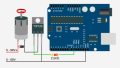
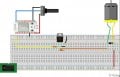
I'm really dumbing things down now so I attached a fritzing diagram, mostly because I'm a visual person and this works for me. How much of this is correct, and what and where do I need to add things - caps, etc?
 

Attachments

Last edited:

THE_RB

Joined Feb 11, 2008
5,438
Well done! That looks totally correct to me.

It does need a power cap (470uF) adding between the transistor E pin (gnd) and the red +pwr wire. And of course you know a breadboard is not ideal for current paths etc.

The TIP120 transistor is pinout BCE looking from the front so you got that all ok. The 1k resistor is optional, because the microcontroller should output a 0v for logic LO so will hold the transistor OFF. But adding the 1k resistor is a nice touch, that keeps the transistor off if the micro PCB is unplugged etc.

From a noise viewpoint you could make a couple of tweaks. I would solder the diode directly across the motor terminals to keep PWM recirculating current local to the motor, and I would add a small poly cap from B-E of the transistor (parallel to your 1k resistor).

Those little DC motors prefer a low freq PWM, so the small cap will give slower turn on/off times which reduces the radiated noise from turn on/off events.

You will need to operate the micro at low PWM frequency, things like portable drills etc run at a couple hundred Hz. Up to 1kHz should be fine provided you don't get too much audible noise at the motor. Cap of 0.1uF or 0.22uF should be fine.

On the other hand if you want to use high freq PWM the cap size will need to be carefully chosen and much smaller.

I suggest a low freq PWM. You will have less electrical noise issues and better torque at low motor speeds.
 
Top