 Facebook
 Google
 GitHub
 Linkedin
After building a linear current limited power supply (1.2V-26.9V, max 1A) which is powered by an SMPS brick, I am in the process of testing the load regulation.
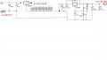
When connecting an adjustable constant-current load at the output (see attached schematic where I have circled this positive output point in red) I've found the load regulation to be over 3% in some cases. I found that when connecting the load and taking measurements directly off the LM138K TO-3 package the load regulation was significantly lower (0.1442% to 1.6184% @1A depending on the output voltage).
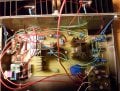
I am thinking that because I used smaller traces when designing the PCB (see attached), and wires going from the LM138K TO-3 package to the PCB, and wires at the output, there are several points where voltage is being dropped (if I connect the load at the circled output point).
When connecting the positive of the load to the circled output point, and taking my voltage measurement directly off the positive output on the TO-3 package, the results were not the same as having both the load and meter directly on the TO-3 output. Why is this?
I would think if voltage is being dropped between the output of the TO-3 package and the circled output point, if I take my voltage measurement at the TO-3 output, it would be the same as having both the load and DVM directly connected to the TO-3 output.
When connecting an adjustable constant-current load at the output (see attached schematic where I have circled this positive output point in red) I've found the load regulation to be over 3% in some cases. I found that when connecting the load and taking measurements directly off the LM138K TO-3 package the load regulation was significantly lower (0.1442% to 1.6184% @1A depending on the output voltage).
I am thinking that because I used smaller traces when designing the PCB (see attached), and wires going from the LM138K TO-3 package to the PCB, and wires at the output, there are several points where voltage is being dropped (if I connect the load at the circled output point).
When connecting the positive of the load to the circled output point, and taking my voltage measurement directly off the positive output on the TO-3 package, the results were not the same as having both the load and meter directly on the TO-3 output. Why is this?
I would think if voltage is being dropped between the output of the TO-3 package and the circled output point, if I take my voltage measurement at the TO-3 output, it would be the same as having both the load and DVM directly connected to the TO-3 output.
Attachments
-
 69.5 KB Views: 47
 -
 567.9 KB Views: 42
 -
 967.8 KB Views: 41


