LM386 with Voltage Divider @ Input Question

Thread Starter

drmanmachine

Joined Mar 12, 2016
68
I am sorry that you think I was rude to you. You did not explain everything before.

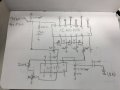
Now you say the LM386 was not clipping. But you said the input was 300mV and the gain was 200. I showed you that the output could not possibly be 300mV x 200= 60V! So of course it was severely clipping.

You did not show your 'scope showing the output of the LM386, instead your scope's timebase was too fast and showed only 8us which is a tiny piece of the output. Please turn down the timebase to show 3 or 4 cycles of the waveform then the timebase will be about 5ms.

Is your 9V battery 9V or has it drained to 6V? The datasheet of the LM386 shows that with a 9V supply and a 4 ohm speaker (your 8 ohm headphones are 4 ohms if both earphones are driven in parallel) the output clips at 3.5V peak-to-peak.
Okay. It was clipping. I took the screenshots really quickly. If I change the timebase to show 3 or 4 cycles, it's going to be difficult to detect what the waveshape looks like. I'll change it to 5ms and take another screenshot.

When my gain was still at 200, I used a battery that was reading about 8.6 volts and I double checked the voltage with a meter. Since then, I removed the cap across the gain pins and applied a fresh 9V battery.
 

Thread Starter

drmanmachine

Joined Mar 12, 2016
68
Just curious. I'm reading on the datasheet that the typical output power is around 700 mW with an 8 ohm load. Could someone tell me if I'm applying my math correctly?

When I apply the power law, I'm receiving this:

P = I^2R
P/R = I^2
SquareRoot(P/R) = I

I = SquareRoot(.700/8) = 296 mA

Then,
P = VI
P/I = V

.700 = V(.296)
.700/.296 = V
V = 2.36 V

Given these typical values of 700 mW and 8 ohms as my load, is this what I should expect as my output current and output voltage?
 

Audioguru

Joined Dec 20, 2007
11,248
The graph in the datasheet of Peak To peak Output Voltage Swing vs Supply Voltage shows 6V p-p when the speaker is 8 ohms and the supply is 9V. Then the RMS for a sinewave is 2.122V and the output power is (2.122V squared)/8 ohms= 0.563W. A squarewave produces twice as much power because it has many harmonics. The peak voltage is 3V so the peak current is 3V/8 ohms= 375mA.
 

Thread Starter

drmanmachine

Joined Mar 12, 2016
68
Here is my drawn schematic. I'm not in front of my circuit right now, but the values should be accurate. Essentially, the 10k pot connecting to pin 3 of LM386 is the one that produces a lot of noise when I'm touching the housing of the actual pot itself. It seems to be the only component to do this. Take a look at it and let me know your thoughts. Thanks.
 

Attachments

Audioguru

Joined Dec 20, 2007
11,248
Connect the pot's housing to ground to stop it from picking up interference.
Why is the pot fed from a voltage divider? You have the squarewave through 100k then it feeds two 10k resistances (one is the pot) in parallel so it attenuates 5k/100k= 1/20th. You do not need the 10k resistor to ground if you replace the 100k resistor with 200k. The input resistance of the LM386 is 50k which will make a small difference.

Your circuit wrongly feeds DC into the pot (then it makes a scratchy sound when turned) and into the LM386 (then its max output level will be half). Use a coupling capacitor (to block the DC but pass the AC) between the output of the squarewave oscillator and the resistor in series with the pot. For frequencies down to 20Hz use 100nF.
 

Thread Starter

drmanmachine

Joined Mar 12, 2016
68
Connect the pot's housing to ground to stop it from picking up interference.
Why is the pot fed from a voltage divider? You have the squarewave through 100k then it feeds two 10k resistances (one is the pot) in parallel so it attenuates 5k/100k= 1/20th. You do not need the 10k resistor to ground if you replace the 100k resistor with 200k. The input resistance of the LM386 is 50k which will make a small difference.

Your circuit wrongly feeds DC into the pot (then it makes a scratchy sound when turned) and into the LM386 (then its max output level will be half). Use a coupling capacitor (to block the DC but pass the AC) between the output of the squarewave oscillator and the resistor in series with the pot. For frequencies down to 20Hz use 100nF.
Just to be sure. Is this what you're suggesting?
 

Attachments

Audioguru

Joined Dec 20, 2007
11,248
I said, "You do not need the 10k resistor to ground if you replace the 100k resistor with 200k." But the un-needed 10k resistor is still there parallel with the pot. The 1uF coupling capacitor is 10 times more, maybe be 10 times larger and maybe 10 times more expensive than the 100nF one I mentioned. It should be a plastic film type, not a polarized electrolytic.
 

Thread Starter

drmanmachine

Joined Mar 12, 2016
68
I said, "You do not need the 10k resistor to ground if you replace the 100k resistor with 200k." But the un-needed 10k resistor is still there parallel with the pot. The 1uF coupling capacitor is 10 times more, maybe be 10 times larger and maybe 10 times more expensive than the 100nF one I mentioned. It should be a plastic film type, not a polarized electrolytic.
Changed. What would the output voltage look like from the 40106? I created the voltage divider to make sure that the input voltage for the 386 wouldn't exceed the maximum rating. Will the 200k and the 10k pot drop the voltage down?
 

Attachments

Audioguru

Joined Dec 20, 2007
11,248
The CD40106 has the output of the first oscillator interfering with the input of the second oscillator and the output of the second oscillator interfering with the input of the third oscillator. The output of the third oscillator has is its output mixed with the first and second oscillators and will be rectangular waves almost 9V p-p. The coupling capacitor blocks the DC so its output is plus and minus 4.5V. The 10k pot parallel with the 50k input of the LM386 makes 8.33k. 200k plus 8.33k makes 208.33k. 4.5V peak into 208.33k produces a current of 0.0216mA. 0216mA into 8.33k produces a peak to peak input to the LM386 of plus and minus 180mV. The LM386 has a gain of 20 times so its output will try to be 180mV x 20= plus and minus 3.6V but with an 8 ohm load it cannot do it, its maximum output shown on the graph in the datasheet will be clipping at plus and minus 3V when the battery is 9.0V and the volume control is at maximum.
 

Thread Starter

drmanmachine

Joined Mar 12, 2016
68
The CD40106 has the output of the first oscillator interfering with the input of the second oscillator and the output of the second oscillator interfering with the input of the third oscillator. The output of the third oscillator has is its output mixed with the first and second oscillators and will be rectangular waves almost 9V p-p. The coupling capacitor blocks the DC so its output is plus and minus 4.5V. The 10k pot parallel with the 50k input of the LM386 makes 8.33k. 200k plus 8.33k makes 208.33k. 4.5V peak into 208.33k produces a current of 0.0216mA. 0216mA into 8.33k produces a peak to peak input to the LM386 of plus and minus 180mV. The LM386 has a gain of 20 times so its output will try to be 180mV x 20= plus and minus 3.6V but with an 8 ohm load it cannot do it, its maximum output shown on the graph in the datasheet will be clipping at plus and minus 3V when the battery is 9.0V and the volume control is at maximum.
Would it make sense then to reduce the input voltage further? Increase the resistance at the LM386 + input to make sure that the output doesn't clip?
 

Audioguru

Joined Dec 20, 2007
11,248
The output from the LM386 is squarewaves since the input is squarewaves. I doubt you can hear the difference when it is clipping, but if you hear clipping then turn down the volume control until it doesn't clip. The clipping level will drop as the battery voltage runs down anyway.
 

Thread Starter

drmanmachine

Joined Mar 12, 2016
68
The output from the LM386 is squarewaves since the input is squarewaves. I doubt you can hear the difference when it is clipping, but if you hear clipping then turn down the volume control until it doesn't clip. The clipping level will drop as the battery voltage runs down anyway.
The end goal is to give this as a gift to a musician friend of mine who is an experimental/noise musician (which makes this application right up his alley) and I'd like him to be able to adjust the volume however way he'd like to. Is it safe to say that the way that I have modified it with your recommendations, it should be good to go for him to use without any continuous issues?
 

Audioguru

Joined Dec 20, 2007
11,248
Now it should work fine if he likes to hear it buzzzzzzz.
Your circuit is old fashioned with manual pot controls for frequencies and volume. Modern circuits use automatic frequency sweeps and volume levels that are stored in a memory IC.
 

Thread Starter

drmanmachine

Joined Mar 12, 2016
68
Now it should work fine if he likes to hear it buzzzzzzz.
Your circuit is old fashioned with manual pot controls for frequencies and volume. Modern circuits use automatic frequency sweeps and volume levels that are stored in a memory IC.
I realize that. I just wanted to go old school with this. I’m looking at this as a learning opportunity. I tried grounding the housing of the pot, but couldn’t get solder to flow onto the housing.
 

Audioguru

Joined Dec 20, 2007
11,248
I looked at page 2 of the Outer Space circuits but it says it will reduce my flatulence that I like to make music and stink bombs with.;)
The circuit uses some of the same CD40106 oscillators as used here but it also uses some analog lowpass filters to smooth the raspy edges of the squarewaves and produce linear sweeps instead of the abrupt frequency changes on this circuit.
 

Thread Starter

drmanmachine

Joined Mar 12, 2016
68
Audioguru, you mentioned that I should ground the housing of the 10k potentiometer to remove any static that occurs when I make contact with it with my fingers. I can't seem to flow any solder on it. I'm just curious on why I would be getting static noise to begin with? If one of the pots pins are already connected to ground. Just curious.
 

Audioguru

Joined Dec 20, 2007
11,248
Audioguru, you mentioned that I should ground the housing of the 10k potentiometer to remove any static that occurs when I make contact with it with my fingers. I can't seem to flow any solder on it. I'm just curious on why I would be getting static noise to begin with? If one of the pots pins are already connected to ground. Just curious.
I circled a solder joint that looked like it held down the metal bracket. It looked like that solder joint connected the bracket to the large expanse of copper ground on the pcb. A wire should be connected to the housing of the pot and connected to the bracket's grounded solder joint.

Your body picks up hum interference from mains electricity all around you and buzz from light dimmers and electric motors. When you touched the housing of the pot you allowed the interference picked up by your body to go into the pot due to capacitance between the housing and the pot terminals. It is interference, not static.

One end of the pot might be connected to the circuit ground but the other end is at the maximum volume position and it picks up interference from the housing due to capacitance if the housing is not grounded.
 
Top