LM358 VCC

Thread Starter

muno

Joined May 17, 2022
95
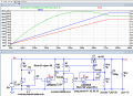
Hi, i have the schematic below i downloaded from a YT video, its a power supply circuit. it uses the lm358 op amp. notice that the datasheet of lm358 can handle upto 32V vcc. my problem is my power supply at the filter cap is having 40v, which i think its a lot for lm358 vcc, how can i lower it so that it will be suited on the lm358 vcc? take note that i will be building a 30v 3a linear bench ps, and i want to copy the schematic below. thanks
 

Attachments

Last edited:

MisterBill2

Joined Jan 23, 2018
27,513
Use a power-tab voltage regulator like the 78 24 to provide a stable voltage that will not fry the LM358.
But I would not trust a youtube circuit to work, especially this one. Running a device at the abs max voltage rating is seldom a good choice.
 

ericgibbs

Joined Jan 29, 2010
21,439
hi Ron,
I 'think' he intends connecting the +40V input to the input marked as +30Vin.
If he reduces the supply to the LM358 to 30V, he will have to make some modifications to left side circuitry, considering the LM358 Vout swing range will be limited.
E

Screenshot_2022-08-30-15-28-09-591_com.google.android.youtube.jpg
 

AlbertHall

Joined Jun 4, 2014
12,625
Use a power-tab voltage regulator like the 78 24 to provide a stable voltage that will not fry the LM358.
But I would not trust a youtube circuit to work, especially this one. Running a device at the abs max voltage rating is seldom a good choice.
But to get 30V output the LM358 outputs must get to 30V.
 

Thread Starter

muno

Joined May 17, 2022
95
hi Ron,
I 'think' he intends connecting the +40V input to the input marked as +30Vin.
If he reduces the supply to the LM358 to 30V, he will have to make some modifications to left side circuitry, considering the LM358 Vout swing range will be limited.
E

View attachment 275118
exactly, since lm358 vcc max input is 32V, which in my case i have 40V, which if i connect lm358 vcc(pin 8) will too much
 

Thread Starter

muno

Joined May 17, 2022
95
Use a power-tab voltage regulator like the 78 24 to provide a stable voltage that will not fry the LM358.
But I would not trust a youtube circuit to work, especially this one. Running a device at the abs max voltage rating is seldom a good choice.
i choose this diagram because it uses tl431 and op-amp. which i think is a versatile one?
 

dl324

Joined Mar 30, 2015
18,326
exactly, since lm358 vcc max input is 32V, which in my case i have 40V, which if i connect lm358 vcc(pin 8) will too much
Use a zener diode to provide V+ to the opamp.
1661869582263.png
If the 40V isn't regulated well enough, you'll need a larger capacitor.
 
Last edited:

ronsimpson

Joined Oct 7, 2019
4,691
Back in 1980 I built this supply. I used a uA723 IC. I also had problems with 40V like this supply.
I added a 10V calculator adapter to power the IC. The 10V supply, negative went to the output or Emitter of the power transistor. The IC turns on the Power Transistor from the +10V supply. The feedback was a little hard to understand. I looked for a schematic but could not find it. I am certain it is in an application note somewhere. I also made a 500V version (low current) using the same floating 10V supply. Maybe a search for uA723 high voltage supply will turn up the design.
 

dl324

Joined Mar 30, 2015
18,326
take note that i will be building a 30v 3a linear bench ps, and i want to copy the schematic below
That may be problematic using LM358 as the control element because the output voltage can only get to within 3-5V of the maximum output voltage for the opamp. What is the lowest output voltage you want?
 
Last edited:

crutschow

Joined Mar 14, 2008
38,504
The MC33171 is a low-cost, single-supply, 44V op amp, which should replace the LM358 without problem.
(Edit: It also generally has better performance with lower power, slightly higher output voltage, nearly double the frequency response, four times the slew-rate, and no crossover distortion.)

Adding a second diode in series with D2 should allow a slightly higher maximum output voltage.
 
Last edited:
Top