Thread Starter

LiftedResearch

Joined Aug 16, 2021
7
Hello all,
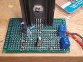
This is my first post so forgive me if I break any rules, I am trying to create a variable voltage power supply using an lm317 but am running into problems. For starters, it doesn't seem that I have a vref voltage, when probed I get 0 volts across input and adjust. My second problem, which I imagine is related to the lack of Vref, is that the output voltage is roughly 1.2 to 2 volts less than the input voltage. These problems are consistent across multiple lm317s and i have checked for any cold joints or open circuits. Perhaps it is the placement of the the components that is causing all of this. Is the 1.25 reference voltage created by the chip itself or by R1? How should adjust be connected to output? I am using a 330 ohm for R1 and 10k pot for R2, along with the recommended capacitors and diodes and the schematic in the datasheet. If any of you could help me or point me in the right direction it would be much obliged.
Thank you,
Jacob
 

dl324

Joined Mar 30, 2015
16,845
Welcome to AAC!

Normally I don't ask for pictures of how things are wired, but they'd be useful in this case. A schematic would also be helpful because some datasheets might not use the same component designators for the current set resistor and the one that provides the step.

LM317 come in several packages. Which are you using?

What is the source of these LM317's? Are they from a reputable source (which wouldn't include eBay, Amazon, Ali Express, etc)?

Perhaps it is the placement of the the components that is causing all of this. Is the 1.25 reference voltage created by the chip itself or by R1?
The reference is generated internally. 330 ohms is too large, unless you have another load on the regulator output. The datasheet specifies a minimum current of 10mA for the regulator to function. It will often work with less, but sometimes needs more than 10mA to work.
How should adjust be connected to output?
From the ADJ pin to ground. It's not connected to the output.
 

Thread Starter

LiftedResearch

Joined Aug 16, 2021
7
What is your voltage source,?
Show your circuit.
Ive been trying three voltage sources a 9v, 24v, and 48v power supply. In the picture I removed the pot (and the diode as well to do so) because the pot was burned out, though I checked that that wasn't the source of the problem. The new resistors are a 5k and 2k in series.
 

Attachments

Thread Starter

LiftedResearch

Joined Aug 16, 2021
7
Welcome to AAC!

Normally I don't ask for pictures of how things are wired, but they'd be useful in this case. A schematic would also be helpful because some datasheets might not use the same component designators for the current set resistor and the one that provides the step.

LM317 come in several packages. Which are you using?

What is the source of these LM317's? Are they from a reputable source (which wouldn't include eBay, Amazon, Ali Express, etc)?

The reference is generated internally. 330 ohms is too large, unless you have another load on the regulator output. The datasheet specifies a minimum current of 10mA for the regulator to function. It will often work with less, but sometimes needs more than 10mA to work.
From the ADJ pin to ground. It's not connected to the output.
Im using the to220 lm317t, I've gotten them from several suppliers, some were Amazon sourced, but others came from a store called Allelectronics.com, though I go to their store and was told they buy them from digikey and mouser. I used the TI circuit provided below. I SmartSelect_20211005-140240_OneDrive.jpgknow the pictures are crap and you can't really see the circuit, especially because some of the pins are connected underneath.
 

Thread Starter

LiftedResearch

Joined Aug 16, 2021
7
This is the circuit as it was originally, though I left out the capacitor, diodes, and input power supply for visibility. How exactly is the adj pin connected to the output? Is it through R1? Could I just solder the two resistors in series to ground and then attach the output in between R1 and R2? 16334695621157968317641643312145.jpg
 

Thread Starter

LiftedResearch

Joined Aug 16, 2021
7
The 1.25V reference voltage will be between the output (+) pin and the Reference pin (-).

And why are you using 330Ω instead of the 240Ω shown in the TI diagram?
Yeah, I you are correct, thought on my setup it is more like 0.8v to 1v than 1.25v. What could be causing that? I'm using 330Ω just because it along with the 10k pot I am using gave the range I wanted, and was more convenient as I had it on hand. Is there an advantage to using the 240Ω resistor? What is the max resistance I should use?

I know the datasheet specifies 0.1μF input, 10μF Adj, and 1μF output capacitors, but should I use higher values for higher currents and voltages? And if so how do you recommend I calculate those values?

P.S. I forgot ti mention that I initially used a lm317HV on my first try with the 48v supply, after it didn't work I moved to the lm317t because I wanted to limit as many variables as possible.​
 

Thread Starter

LiftedResearch

Joined Aug 16, 2021
7
Another question I have is regarding the LM317's ability to work with higher voltages, as said in the datasheet:
"regulator is floating and receives only the input-to-output differential voltage, supplies of several hundred volts can be regulated as long as the maximum input to output differential is not exceeded"
How does this work exactly? For what voltage range is this true? Is it setup just like usual except the ground would be difference of the output voltage and the input voltage (including the 3v headroom)? Would the current through the resistors be the same, or proportional to the higher voltage? Also I forgot to add this in my last post, what happens if the minimum output current is not met? Does the voltage still get regulated or does it rise to the input voltage less the 1.25v or 3v reference/headroom?
 

crutschow

Joined Mar 14, 2008
34,281
you are correct, thought on my setup it is more like 0.8v to 1v than 1.25v. What could be causing that?
If you are using 330Ω and don't have an additional load to make at least 10mA output current, that might cause the variation.
It should be a solid 1.25V with no variation.
I'm using 330Ω just because it along with the 10k pot I am using gave the range I wanted, and was more convenient as I had it on hand. Is there an advantage to using the 240Ω resistor? What is the max resistance I should use?
You can use that or a somewhat higher resistance as long as the load current is at least 10mA.
The limit is determined by the voltage error caused by the ADJ bias current through that resistance.
Its value should be no more than 120Ω if you want to have it maintain regulation with no load.
 

dl324

Joined Mar 30, 2015
16,845
How does this work exactly? For what voltage range is this true?
The maximum voltage specification is for input to output. If the input voltage was 60V and the output voltage was 50V, you'd be well within the maximum voltage specification. The datasheet should make that clear.
Also I forgot to add this in my last post, what happens if the minimum output current is not met? Does the voltage still get regulated or does it rise to the input voltage less the 1.25v or 3v reference/headroom?
The regulator isn't guaranteed to regulate voltage with less than 10mA load current. Many will work with less, and some might take more. I had one that required 20mA before it would work.

If you don't buy from reputable places, you're more likely to have problems with substandard parts.
 

Audioguru again

Joined Oct 21, 2019
6,672
And why are you using 330Ω instead of the 240Ω shown in the TI diagram?
240 ohms is shown on the diagram for the more expensive LM117 circuit. the LM317 needs 120 ohms and its datasheet says that the output voltage will rise if the resistor value is too high when the load current is low.
1.25V/120 ohms= 10.4mA which is slightly more than the 10mA minimum required for an LM317. The LM117 has a minimum current of 5mA.
 

AnalogKid

Joined Aug 1, 2013
10,986
If you put 48V on the input, you would have exceeded the maximum input voltage for a standard LM317 (40V maximum). You risk blowing the regulator in that case.
Incorrect. There is no maximum input voltage (to GND) specified for the LM317. There is a maximum input-output differential voltage spec of 40 V. This is the voltage from the Vin pin to the Vout pin, *not* from the Vin pin to GND. The unique (at the time) characteristic of the 317 is that it has no GND connection; it "floats" in the shunt adjustment resistor. For example, if the input voltage is 370 Vdc, and the output voltage is 350 Vdc, the chip will be perfectly happy.

ak
 

crutschow

Joined Mar 14, 2008
34,281
There is no maximum input voltage (to GND) specified for the LM317.
True.
But for the adjustable regulator the TS was building, the maximum input-output differential (minimum output voltage) would be 1.25V less than the input voltage, so sagor's concern is valid.

Edit: Also, if the output is momentarily shorted, the full voltage is applied across the regulator regardless of it's output voltage setting.
 
Last edited:
Top