LM317 Nightmare

ebp

Joined Feb 8, 2018
2,332
Yes I did. My schematic does not show the .1 uf I mounted at the input. The 100uf at the output was for ripple.
If there is ripple at the output without the 100 µF cap at the output, then there is excessive ripple at the input. The output capacitor lowers the output impedance at high frequency, acting as a charge store to cope with load transients that are fast relative to the response speed of the 317. If there is line-frequency (times 2, normally) ripple remaining at the output then more "bulk" filtering capacitance is required at the input.
 

Marcus2012

Joined Feb 22, 2015
425
Can you post a complete diagram of the circuit you've built please and tell us what the supply is (is this clean DC or rectified AC source), and what load you are trialing this with. You mentioned higher voltages than 24V earlier which appear more like peak AC voltages, is this getting power from a 24Vrms transformer?
 

Thread Starter

electrongod1

Joined Sep 8, 2018
40
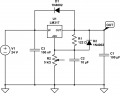
Attached is the circuit. I show a 122 ohm load resistor on output pin. Is actually a 100 ohm and 22 ohm in series. This is a rectified AC voltage source from a center tapped 117v primary/ 24v secondary through a bridge rectifier. Output at the rectifier is 26.7vdc. There is no load on the circuit.
 

Attachments

ebp

Joined Feb 8, 2018
2,332
What are you using for a bulk filter (smoothing) capacitor between the bridge rectifier and the regulator?

EDIT: What is the actual measured AC voltage at the output of the transformer?
 
Last edited:

Marcus2012

Joined Feb 22, 2015
425
The circuit looks ok (other than the wiper of the pot not being connected ;), but i'm guessing it is in the actual circuit), but if it were working the LM317 would need a minimum load of ~ 10mA to function correctly anyway or your voltage readings would be false.
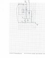
What is your centre tap transformer and rectifier setup like? it shouldn't need a FWB. Is it the same as this with R substituting the regulator/load?


ebp

Joined Feb 8, 2018
2,332
So 0.1 µF is the ONLY capacitor between the rectifier and the regulator?
You must use a substantial amount of capacitance to "filter" or "smooth" the output of the rectifier, otherwise what you will have are pulses shaped like half of a sine wave, with the voltage going to zero between. Each AC cycle will produce two such pulses. A broad rule of thumb is to use about 1000 µF for each ampere of load current, but there are circumstances where more capacitance may be necessary or desirable.

EDIT -forgot you were using a centre tapped transformer

Is the voltage you measured from end to end of the transformer or from one end to the centre tap?
 

ebp

Joined Feb 8, 2018
2,332
I was too hasty removing most of my post at #27,

The peak voltage out of the rectifier will be about
28.3 x √2 - 1.4 = 38.6 V
the square root of 2 is the ratio of peak voltage to RMS voltage for a pure sine wave; most meters either directly measure RMS voltage or used a scaling factor from measured average voltage, assuming a sine wave input. The 1.4 is the approximate voltage drop due to the two diodes in the rectifier.

The filter capacitor will need to be rated at something higher than the expected peak (which can be another few percent higher due to AC line voltage variation). A rating of 50 V is the closed common rating greater than that.

===
Returning to the regulator:
You don't need to use any specific value for the resistor between the output and the ADJ pin. A resistance of 124 ohms is convenient because the regulator maintains a voltage of nominally 1.25 V across that resistor, so the calculation is very simple. But the calculation is simple in any case. Using 124 ohms (a value in the "E96" series of preferred values, which is commonly used for 1% tolerance resistors) also means the minimum load current of 10 mA, as required by the 317 to assure regulation, is always present. You could use just 100 ohms instead, raising the load current to 12.5 mA. The concern that can arise with a value that is too small is that the current through the lower resistor of the divider will be the same (actually very slightly higher due to the current flowing out of the ADJ pin), and that could exceed the power rating of a small potentiometer, if used.

If you are using the regulator without adequate input filtering/smoothing capacitance, the output will look like the right hand waveform at 26 with the tops neatly sliced off at the setpoint voltage of the regulator, provided there is very little capacitance on the output of the regulator. No practical amount of capacitance on the output will properly smooth the output to low ripple.
 

ebp

Joined Feb 8, 2018
2,332
Building (what I thought) is simple variable benchtop power supply. Attached is rectifier circuit. Thanks all.
You will need to add that filter/smoothing capacitor between the bridge and the regulator. 1000 to 2200 µF would be suitable - use the higher value if you want more than 1 A output. If you don't have one rated at 50 V on hand and want to continue to experiment, you can use lower capacitance (but not voltage rating), but you'll need to keep the output current down to something around a milliamp per micorfarad.
 

ebp

Joined Feb 8, 2018
2,332
Something sometimes overlooked when using a potentiometer as a rheostat (simple variable resistor):

A failure mode of pots is for the wiper to go open-circuit, and very rarely this can also happen momentarily while adjusting. For this reason it is always best to connect the wiper to the appropriate end of the potentiometer. That way the resistance, barring major failure, will never be greater than the end-to-end resistance of the pot. With the LM317, if the pot goes open circuit, nearly the full input will be applied to the output. Of course even with the full resistance of the pot in the circuit, the voltage could go high enough to damage what is being powered. This is a an ever-present risk with any power supply.

I'll leave it to you as a little exercise to figure out which end of the pot should connect to the wiper for your circuit.
 

Thread Starter

electrongod1

Joined Sep 8, 2018
40
Something sometimes overlooked when using a potentiometer as a rheostat (simple variable resistor):

A failure mode of pots is for the wiper to go open-circuit, and very rarely this can also happen momentarily while adjusting. For this reason it is always best to connect the wiper to the appropriate end of the potentiometer. That way the resistance, barring major failure, will never be greater than the end-to-end resistance of the pot. With the LM317, if the pot goes open circuit, nearly the full input will be applied to the output. Of course even with the full resistance of the pot in the circuit, the voltage could go high enough to damage what is being powered. This is a an ever-present risk with any power supply.

I'll leave it to you as a little exercise to figure out which end of the pot should connect to the wiper for your circuit.
Cool! Now I'm getting somewhere. Allways suspected my pot (having replaced it several times). To answer your exercise, I would think the wiper would be connected to the 0v (ground) side of the circuit. Could I also mount a small resistor between wiper and pot input to prevent this possibility, understanding the change to the total resistance of the pot. I love exercises, not answers. How I learn. Thanks.
 

ebp

Joined Feb 8, 2018
2,332
Could the lack of properly sized capacitor between rectifier and regulator burn up R1?
That's a question I can't answer with any certainty. With the capacitor across the pot and the diode, the capacitor could be discharged almost completely each AC half cycle, then recharge during the first part of the next half cycle. The discharge would be primarily through the diode be the charging would be through R1. This might increase the power in the resistor enough to burn it up, depending on the setpoint voltage of the regulator (since the cap charges to 1.25 V less than the setpoint when "in regulation").

Perhaps one of the AAC members who is proficient with LTSpice would run a simulation to evaluate this for you. Hint, hint :D


LTSpice is a powerful simulation software package that is available free from Analog Devices (possibly renamed now, since Analog acquired Linear Technology). Lots of people at AAC use it. I don't, but only because I no longer actually do electronics. It looks to me like one of the most valuable free software packages for electronics that exists. Simulation has its limits, but it gives you the equivalent of a whole lab full of instruments to measure what goes on in circuits and produce numerical and graphical output. And of course you can build all sorts of experimental circuits without buying any parts. Experimentation with real parts is invaluable, but I think these days simulation is invaluable too.
 
Top