Facebook
 Google
 GitHub
 Linkedin
Hi everyone,
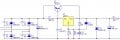
I want to make a variable power supply with lm317/338 and a PNP pass transistor. I need a max output of 2.5-3A and 1.25-28V. I will use the transistor for its better power dissipation. The problem is that in this way the short circuit protection of the regulator is useless.
Here i found a schematic (2nd one) that deals with this problem by using a resistor in the emitter, but i didn't quite get the principle of operation so i can change the values for my requirements.
http://www.bowdenshobbycircuits.info/page12.htm
I also want to change the 0.7ohm resistor to a bigger value, so that the regulator won't be needing a cooling heat sink, at least not very big one.
Any ideas?
edit: I didn't get the title quote right, but i think you get the idea