Linear regulator with a pass transistor protection.

Jony130

Joined Feb 17, 2009
5,598
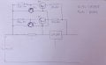
The author simple assumes that lm317 will enter into short circuit protection mode if lm317 output current is larger then 2A. So 0.7Ω voltage is 2A*0.7Ω = 1.4V and this also means that the emitter current is equal to Ie = (1.4V-Vbe)/0.3Ω = (1.4V - 0.7 V)/0.3Ω = 2.3A. So the load current is Iload = Ie + Ilm3172 = 2A + 2.3A = 4.3A
But I do not like this circuit. Try this circuit
http://www.eleccircuit.com/wp-content/uploads/2009/08/regulator-booster-by-transistor.jpg
 

Thread Starter

illusive

Joined Jul 9, 2015
46
Hmm, thanks Jony, this circuit might just work!
So in theory if i put 0,39ohm in R2 the transistor will be limited to about 1,7A, right ?
 

Thread Starter

illusive

Joined Jul 9, 2015
46
This is pretty much my final design. What do you think? I just can't settle down on the regulator resistor value. I want when i'm drawing the maximum current (2.5A) from the circuit, the current through LM317 to be no more then 100-150mA.
 

Attachments

ronv

Joined Nov 12, 2008
3,770
@illusive
The pass transistor part is an ok idea, but trying to maintain the current limit is probably not going to work. :(
Here are a few things to think about:
You have a very high input voltage, so when you have the output set at a low voltage and the high current everything has to work hard.
So let's start with the 317. It has a maximum junction temperature of 125C and the rise of the junction to the case is 5C per watt. So I use an example of a heatsink of 6C per watt. That would say the maximum current for the 316 would be about .3 amps. if the output is 5 volts. 0.3a X 29v = 9 watts. So the heatsink will go to 54C plus 25 for ambient or 80C. The junction will be 45C higher at 125.
Toasty....:D But let's say we go for it.
So we have .3 amps from the regulator, so we need 2.7 from the transistor.
The reason you are having trouble calculating the resistor is because you are missing the gain of the transistor. The gain of the 2N2955 is a minimum of 20, so to get 2.7 amps out you need .135a of base current. Lets leave out the emitter resistor to make it easier. If we make the resistor4.3 ohms at .3 amps it will drop 1.29 volts, but it takes .7 volts (about) to turn on the base emitter junction of the transistor so we have .59 volts across 4.3 ohms or 137 ma to drive the transistor times a gain of 20 is 2.7 amps. So now the current limit works because the 317 will go into thermal limit if we try to draw more current so the base drive for the transistor cant go any higher either. Life is good.:rolleyes:
But...... The gain of the 2N2955 could be as high as 70, which means with the same .135 amps it could support 9.5 amps. Way to many watts.
So rethink your specs. Do you really need 28 volts? Do you really need 3 amps at 5 volts?
There are ways to do it but this way is not the best. Let us know if you want to look at other ways.
 

Thread Starter

illusive

Joined Jul 9, 2015
46
I want in case of an output short the current to be about 2.5-3A so i do not blow the transistors. The power supply will be rаrеly used above 2A in normal operation.

The problems i'm trying to solve are in case of shorted output the transistor to not blow and in worst case scenario (5V otput, 2-2.5A) to not overheat. I repeat, this is worst case scenario, i'm doing it just to be safe.
The heat sink that i have is with fan and i think it has about 0.6-0.7°C/W thermal resistance.
Is it worth the shot ?
 

ronv

Joined Nov 12, 2008
3,770
Let's look for a better way.
I think you talked of a plus/minus supply. How were you going to do it? With one transformer or 2 different ones?
 

Thread Starter

illusive

Joined Jul 9, 2015
46
Well i have one transformer with two separate windings 2x12V.

Btw, i wired up the schematic with just one power transistor to test the concept. The smaller transistor is limiting the current in short circuit condition pretty much as expected.It gets a bit hot after a while but that's not a problem because it is supposed to stay in this limiting state for no more than a second or two. The regulator resistor i used was 56ohm. With no load the LM317 is drawing 10mA and it is producing about 0.6V across the resistor and thus the power transistor i just about to start conducting.
 

Thread Starter

illusive

Joined Jul 9, 2015
46
OK, i have tested this circuit and when shorted the output current is about 4,4A. Isn't that a bit too high? Am i missing something?
P50716-030746.jpg
 

ronv

Joined Nov 12, 2008
3,770
OK, i have tested this circuit and when shorted the output current is about 4,4A. Isn't that a bit too high? Am i missing something?
View attachment 88592
The way it is right now the little transistor try's to supply all the current once the current is high enough to turn it on.
Try making the 56 ohm 15 ohms and the .47 .22 ohms. Then add a 100 ohm between the junction of the 317 and 15 ohm and the base of the power transistor.
 

Thread Starter

illusive

Joined Jul 9, 2015
46
With the 15 ohm resistor i get several volts drop across it and the supply voltage to lm317 drops a lot.
Hmm, this is more tricky then i thought. I'm starting to look around for another approach. ronv, maybe you are right, i need a better way.

Here are again my requirements. I have a 24VAC 100VA transformer.I need a regulated output up to about 24-28V and maximum output current of 2-2.5A. I need some sort of current limiting/short circuit protection so when i accidently short the outputs i don't get to blow the transistors or the regulator.

The circuit from the Nat Semi Voltage Regulator Handbook looks pretty straight forward. I'm thinking around 10ohm for R2 and 0.47ohm for R1 and according to the formula this should limit the current to about 2,5A with some adjusting of values.


Another option is something with LM723.
http://www.eleccircuit.com/regulator-0-30v-5a-by-ic-723-2n3055-2part/

Or maybe a switching regulator with LM2596 ?

I was also thinking of paralleling 3 lm350's and a relay at the output and with a short circuit comparator or something like that to open the relay and cut out the load. The power supply should should withstand about 10ms until the relay activates.

This seemed to me a quite popular diy project but i still can't find a proper solution.

I really appreciate your time guys, you are really helpful.
 
Last edited:

ronv

Joined Nov 12, 2008
3,770
It was this statement in your first post that keeps it from working.
I also want to change the 0.7ohm resistor to a bigger value, so that the regulator won't be needing a cooling heat sink, at least not very big one.
It's the protection built into the regulator that is used to protect the transistor.
If you want to let the 317 work harder it can work, but it is still touchy.
 

Thread Starter

illusive

Joined Jul 9, 2015
46
OK, i will mount the lm317 to the main heat sink, but there is still shouldn't be too high current through it or it will overheat. I have two PNP transistors tip2955. How it will all fit together? I have two options: Limit somehow the current to 2.5A max and call it a day or if this is too difficult then limit it to 3A, 4A of even 5A just so the transistors doesn't damage of overheat until a relay cuts of the load.
 

Thread Starter

illusive

Joined Jul 9, 2015
46
Based on the info i got from here:
http://homepages.which.net/~paul.hills/Circuits/PowerSupplies/PowerSupplies.html
I simulated a bit reworked circuit and all seems OK. I set it up to limit the current to about 3A max. When the total output current is 2.5A the current through the regulator is about 500mA which i think will be fine (that gives me 12-13W of power dissipation in the chip at worst case scenario).
testsim.jpg

What do you think?
 

Thread Starter

illusive

Joined Jul 9, 2015
46
After further testing it doesn't seem to work as intended. It's just too hard to limit the total current to about 2.5-3A when short circuit. I'm officially in dead end :D
 

Thread Starter

illusive

Joined Jul 9, 2015
46
OK, sorry for the multiple posts but i have a question.
ronv, you got me thinking about dual power supply. My transformer is with two separate winding so it should be easy.
If i use two LM350's in this configuration:

and lets say i connect the load between the positive and the negative rail(the 0 rail of the first supply is going to be connected in series to the + rail of the second supply of course), how is the power dissipation distributed?
 

crutschow

Joined Mar 14, 2008
38,536
Regarding the capacitors across the rectifier diodes... In general I think they're unnecessary at line frequencies. The diodes in this schematic are ultra fast rectifiers with reverse recovery times of 60nS, so even in high frequency applications (e.g. switching regulator) paralleling with caps is probably unnecessary.
The caps are likely for EMI and noise reduction since they suppress the noise from the sharp turn-off of the diodes when they become reverse biased each cycle.
Standard slow turn-off diodes are actually better the fast recovery diodes for standard line frequency rectifiers from a noise point-of-view.
 

Jony130

Joined Feb 17, 2009
5,598
Simulations says that only this circuit is able to limit the current to the value you want (1.65A).
View attachment 88603
Maybe tomorrow I find the time and test this
OK, sorry for the multiple posts but i have a question.
ronv, you got me thinking about dual power supply. My transformer is with two separate winding so it should be easy.
If i use two LM350's in this configuration:

and lets say i connect the load between the positive and the negative rail(the 0 rail of the first supply is going to be connected in series to the + rail of the second supply of course), how is the power dissipation distributed?
For the same load and the same voltage the power dissipation will be equal. For example for RL = 100Ω and Vout = 10V ( 5V in first and 5V in second) and Vin = 15V we have:
Ptot_in upper_LM = (15V - 5V) * 10V/100Ω = 1W
Ptot_in_lower_lm = (15V - 5V) * 10V/100Ω = 1W


.
 

Thread Starter

illusive

Joined Jul 9, 2015
46
So if i'm willing to sacrifice my output voltage to 24V (2x12) i will get away with the power dissipation? For example if i set the output voltage to 10V total and im drawing 2.5A the power dissipation will be split between the two regulators and it will be for each regulator Vin from the transformer about 15V - 5V output = 10V*2.5A = 25W is that right ? I think my idea is wrong here.
power-supply-two-times-20v-and-5a-using-lm338.gif
this circuit isn't mine. My transformer is 2x12VAC.
 
Top