Lighting LEDs with a wide range of Celcius values using thermal switching

wayneh

Joined Sep 9, 2010
18,133
For grins I was going to whip up an example of using LM35 and LM3914 for this. I got blocked at the first step - finding an LTspice model for the LM3914. I could find only two, one here and one by our own @Alec_t here! (Maybe a third one here.) But I'm not a member there and cannot download it. It doesn't appear to be duplicated here in AAC. Hint hint.
 

Thread Starter

Ja Jang Myeon

Joined Nov 2, 2018
16
The question about the LEDs is what is the voltgae and current for each one? For example, if these are single, small LEDs then the voltage drop across them is called the forward voltage, with the symbol Vf. For standard little red, yellow, and green LEDs it usually is around 1.8 V to 2.1 V, with a standard operating current of 20 mA. White and blue LEDs usually have higher Vf values.

With this information we can determine whether or not a sensor chip or comparator circuit can drive the LEDs directly, or if we need to add a driver transistor (current amplifier) to get full brightness.

ak
These are the LEDs I have to work with, they are all from Kingbright:

Red: APD3224SURCK-F01, Forward Current=20mA, Forward Voltage=1.95
Blue: APD3224QBC/D-F01, Forward Current=20mA, Forward Voltage=3.3
Yellow: APD3224SYCK-F01, Forward Current=20mA, Forward Voltage=2.0
Green: APD3224MGC-F01, Forward Current=20mA, Forward Voltage=2.1

Is that enough information? I usually get all of my stuff through Mouser and the information above is from their site.
 

AnalogKid

Joined Aug 1, 2013
12,238
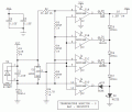
First pass, probably needs tweaking. Use an LM239 or 139 for the non-commercial temperature range.

For Vcc = 24 V, R1 sources approx. 2 mA through U2, the system voltage reference. This is more than enough for some current to be drawn off by other circuit elements: the reference divider string draws approx. 100 uA, and the LM35 draws 133 uA worst case.

The reference voltage is 4.096 V. For a reference divider string current of 100 uA, the total resistance should be 40,960 ohms. The actual resistance of the divider string is 40,670 ohms, less than 0.7% error. With a string current of 100 uA, every 1K in value equates to 10 degC. This makes the resistors that separate the trip points easy to calculate. The LM35 makes 0 V at 0 C. D1 elevates the LM35 output so the output from the LM35 can go negative (with respect to its own reference pin, pin 3) to assure that U1D is off when temperatures are below 0 C. The idea and the equation for R6 are in the LM35 datasheet.

The five LEDs are mutually exclusive, only one on at a time. If the temp is below 0, all comparators are off (output is open collector, not sinking any current). In this state, D2 is powered by R7 through D7, D8, D9. Vf across D2 is over 3 V. When the temp rises above 0 C, U1D comes on, pin 13 goes low, and D3 is powered through the same diode string. Because D3's Vf is much lower than D2's, it effectively "shorts out" D2, turning it off. When the temp rises above +25 C, U1C comes on. Now the cathode of D4 is near GND, and its Vf is lower than either D7 + D3 or D7 + D2. D4 hogs all the current, and both lower LEDs remain off. Same for D5 and D6 as the temperature increases. Since only one LED is on at a time, only one current limiting resistor is needed. The current for each increasing LED is a bit higher than the one before it, but the overall variation is less than 20%.

Note - D2/D3 switching works only if the two Vf values differ by more than 0.5 V. Let us know the white LED Vf value.

Note - There is no hysteresis around the comparators - on purpose. Flickering between two LEDs indicates that the temperature is right at the transition value for the higher of the two.

UPDATE - R6 can be changed to 2.49K. 14.3K is the maximum value calculated for 0 C. The minimum value can be much smaller (something like 50 ohms at -10 C).

ak
Temp-Mon-2.gif
 
Last edited:

Thread Starter

Ja Jang Myeon

Joined Nov 2, 2018
16
First pass, probably needs tweaking. Use an LM239 or 139 for the non-commercial temperature range.

For Vcc = 24 V, R1 sources approx. 2 mA through U2, the system voltage reference. This is more than enough for some current to be drawn off by other circuit elements: the reference divider string draws approx. 100 uA, and the LM35 draws 133 uA worst case.

The reference voltage is 4.096 V. For a reference divider string current of 100 uA, the total resistance should be 40,960 ohms. The actual resistance of the divider string is 40,670 ohms, less than 0.7% error. With a string current of 100 uA, every 1K in value equates to 10 degC. This makes the resistors that separate the trip points easy to calculate. The LM35 makes 0 V at 0 C. D1 elevates the LM35 output so the output from the LM35 can go negative (with respect to its own reference pin, pin 3) to assure that U1D is off when temperatures are below 0 C. The idea and the equation for R6 are in the LM35 datasheet.

The five LEDs are mutually exclusive, only one on at a time. If the temp is below 0, all comparators are off (output is open collector, not sinking any current). In this state, D2 is powered by R7 through D7, D8, D9. Vf across D2 is over 3 V. When the temp rises above 0 C, U1D comes on, pin 13 goes low, and D3 is powered through the same diode string. Because D3's Vf is much lower than D2's, it effectively "shorts out" D2, turning it off. When the temp rises above +25 C, U1C comes on. Now the cathode of D4 is near GND, and its Vf is lower than either D7 + D3 or D7 + D2. D4 hogs all the current, and both lower LEDs remain off. Same for D5 and D6 as the temperature increases. Since only one LED is on at a time, only one current limiting resistor is needed. The current for each increasing LED is a bit higher than the one before it, but the overall variation is less than 20%.

Note - D2/D3 switching works only if the two Vf values differ by more than 0.5 V. Let us know the white LED Vf value.

Note - There is no hysteresis around the comparators - on purpose. Flickering between two LEDs indicates that the temperature is right at the transition value for the higher of the two.

UPDATE - R6 can be changed to 2.49K. 14.3K is the maximum value calculated for 0 C. The minimum value can be much smaller (something like 50 ohms at -10 C).

ak
View attachment 169915
Sorry for the delay, had to take a short trip.
OMG, what a masterpiece!!! You people are awesome! I only wish I could have come up with that. And no microprocessors/code to worry about--straight bare-metal solution. Amazing!
I looked at the inventory for the white LEDs that come closest to the other in terms of size and specs and I think this one will do: (Mouser Part#) 743-IN-S124BRUW. The LED has a 20mA Forward Current and 3.3V Forward Voltage. If that is ok, I will go with that, if not and something would work better please let me know.
 
Last edited:

Thread Starter

Ja Jang Myeon

Joined Nov 2, 2018
16
That is the same as the blue LED. Add another 1N914 (1N4148, 1N4004, whatever) in series with the white LED between its cathode to GND.

ak
Yes, you're right, the LM139 series has a better temperature range for this application. I see on the Mouser site there are a number of variants of the LM139. Assuming SMD types, is there a part number you'd feel wold be most effective (I don't know the difference between open drain and rail-to-rail). I have about 20 LM139AD units on hand.

As for the LM4040 I have a handful of the LM4040A41IDBZT, these components are expensive. Curious.

Thanks to all, especially AnalogKid!
Feels like Christmas in February!
 
Last edited:
Top