Running LEDs with no resistors

Thread Starter

Mickey12

Joined Oct 10, 2026
7
I’ve made 2 DIY LED projects. Neither of which have resistors installed.

  • Project one is powered by a 9v AC/DC adapter with 1.2A MAX with 9 multicolored LEDs. Power is run thru a 6-way splitter and then out to the LEDs
  • Project Two is powered by a 12 AC/DC adapter with a 2.0A Max with 8 multicolor LEDs Power is run thru a 6-way splitter and then out to the LEDs.
  • LEDs are garden variety type 0.25w consumption.
Both projects have been run for a number of hours without burnout or overheating. Have I been lucky or what? Every internet site says to put a resistor on a LED circuit. If so, what size? And should I have one for each LED lamp?
 

Attachments

MrChips

Joined Oct 2, 2009
35,214
To be honest, we don't know the current and voltage requirements of each LED. We also don"t know the function of the 6-way splitter and what it is supposed to do. Is it suppose to select one circuit and connected it to the + and - input?

Let us assume that you have 9 LEDs connected in series and on average they run on 20 mA at 2 V.
They would together need 18 V. Hence running them from a 9 VDC power supply means that they are running at lower intensity.

Similarly, 8 LEDs in series would need 16 V. Again, a 12 VDC supply would be driving the LEDs at lower power.
 

WBahn

Joined Mar 31, 2012
33,257
We need a lot more detail on this "6-way splitter" you are using. I have no idea what those components are that are shown in it. Can you provide a data sheet or a manufacturer and part number for it?

Please provide an actual schematic for how everything is connected. It doesn't have to be fancy, it can even be a hand-drawn sketch. Don't make everyone guess.

You say your LEDs are "garden variety 0.25 W consumption". A typical indicator LED, which is what those appear to be, typically consumes 40 mW to 50 mW. So whatever you are using doesn't appear to be "garden variety" if it is consuming 250 mW (which would be more like a 125 mA draw instead of 20 mA). So, can you provide a data sheet or manufacturer and part number for the LEDs you are using?

When you say "multicolor LED", that normally means an LED that can produce more than one color (and which therefore has to be controlled somehow). Is that truly what you mean? Or do you just mean that you are using a bunch of LEDs and they are different colors?

Different colored LEDs have different forward voltages, so putting them truly in parallel will generally result in the one with the lowest forward voltage lighting up and the others remaining dark. The fact that they are all lighting up indicates that either they are not simple LEDs (may have an internal current limiting resistor) or that that power splitter is doing something to isolate the outputs from one another and/or limit the current.

These are all things that need to be addressed before we can really talk about your specific applications there. If you are not using anything to limit the current, then again, either the LEDs are not simple LEDs, or that power splitter is doing that job. In either case, we need more information.

But to talk generically about running LEDs in parallel without individual current limiting resistors, the basic answer is that it's not a good idea, but you can sometimes get away with it, sometimes by design, and sometimes by luck.
 

WBahn

Joined Mar 31, 2012
33,257
okay, let me add some stuff to the mix. thanks for your insights and patience.
1791672499619.png

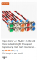
This explains it. These are not bare LEDs, they have current-limiting resistors included. You might even be able to find them, probably under heat shrink on one of the leads of the LEDs.

The resistor is sized to produce a workable current with between 9 V and 12 V applied across the wires. I'm guessing that the 0.25 W is for the highest current draw at 12 V, which would be 20.8 mA, which likely comes from 20 mA rounded up to a nice number.

I'd still like to know more about that power splitter, but as I look more closely at it, what appear to be components in the recesses might just be push button releases for terminal blocks? Does that sounds right?
 

MrChips

Joined Oct 2, 2009
35,214
From what everyone else is saying,

(1) the 6-way splitter is 6 ON/OFF switches that routes power in to each and all outputs in parallel as desired,

(2) the LEDs you are using have built-in current limiting resistors to operate from 9 - 12 VDC, all LEDs wired in parallel with the supply.

What you are doing is fine.
 

WBahn

Joined Mar 31, 2012
33,257
Let us assume that you have 9 LEDs connected in series and on average they run on 20 mA at 2 V.
They would together need 18 V. Hence running them from a 9 VDC power supply means that they are running at lower intensity.
Saying that they would be running at lower intensity, while indisputably true, might also just be the mother of all understatements.

I took a red LED, spec'ed for Vf of between 2.0 V and 2.2 V at 20 mA, and made some measurements.

At 20 mA, the voltage was 2.092 V and it was very bright.
At 10 mA, the voltage was 1.990 V and I couldn't tell the difference (highlighting that humans have a hard time distinguishing factors of two in intensity).
At 2 mA, the voltage as 1.857 V. It was noticeably dimmer, but still quite useable as an indicator in normal room lighting.
At 1 mA, the voltage was 1.822 V.
At 200 µA, the voltage was 1.753 V and it was getting quite dim, but still clearly emitting.
At 2 µA, the voltage was 1.546 V and at this point I had to turn off the room lights and use a magnifying glass looking straight into it to be sure it was emitting.
At 0.5 µA, the voltage was 1.500 V and this was the lowest current that I was able to detect any emission, no matter how carefully I looked (though, at one point, I may have seen something at 0.3 µA).

Below 2 mA, the current was dropping by an order of magnitude for every ~100 mV of voltage drop, which is consistent with a diode having an ideality factor of 1.7, which is very reasonable. Above the current, and it appears that the behavior is becoming increasing dependent on a resistive component, which is also normal for LEDs.

Notice that going from 10 mA to 0.5 µA, a factor of 20,000, dropped the voltage by just shy of 500 mV.

To get down to 1 V across the LED from 1.5 V, we need to drop it by another five orders of magnitude, or down to somewhere in the 5 pA to 10 pA range. The closest measurement I could make with my meters was a 1.100 V with a current of about 190 pA, which would be consistent with 19 pA at 1.0 V across the LED, so very much in the ballpark, especially since at very low currents there are other effects that can start to dominate (including measurement artifacts like surface leakage current).

While I was actually surprised that I could detect (albeit in a dark room, with a magnifying glass, looking straight into the LED) light all the way down to a fraction of a microamp, I would not consider the LED to be "on" in any useful sense below about 20 µA, or about 0.1% of it's nominal current, which was at about 1.65 V (and even this would likely be seen as "off" unless looking carefully).
 

Thread Starter

Mickey12

Joined Oct 10, 2026
7
View attachment 372124

This explains it. These are not bare LEDs, they have current-limiting resistors included. You might even be able to find them, probably under heat shrink on one of the leads of the LEDs.

The resistor is sized to produce a workable current with between 9 V and 12 V applied across the wires. I'm guessing that the 0.25 W is for the highest current draw at 12 V, which would be 20.8 mA, which likely comes from 20 mA rounded up to a nice number.

I'd still like to know more about that power splitter, but as I look more closely at it, what appear to be components in the recesses might just be push button releases for terminal blocks? Does that sounds right?
the + and - wires just push in. thanks great info.
 

Thread Starter

Mickey12

Joined Oct 10, 2026
7
From what everyone else is saying,

(1) the 6-way splitter is 6 ON/OFF switches that routes power in to each and all outputs in parallel as desired,

(2) the LEDs you are using have built-in current limiting resistors to operate from 9 - 12 VDC, all LEDs wired in parallel with the supply.

What you are doing is fine.
thanks that helps a lot
 

Thread Starter

Mickey12

Joined Oct 10, 2026
7
next time you should get something like this so that mounting is simpler/cleaner.
View attachment 372127
View attachment 372124

This explains it. These are not bare LEDs, they have current-limiting resistors included. You might even be able to find them, probably under heat shrink on one of the leads of the LEDs.

The resistor is sized to produce a workable current with between 9 V and 12 V applied across the wires. I'm guessing that the 0.25 W is for the highest current draw at 12 V, which would be 20.8 mA, which likely comes from 20 mA rounded up to a nice number.

I'd still like to know more about that power splitter, but as I look more closely at it, what appear to be components in the recesses might just be push button releases for terminal blocks? Does that sounds right?
the wires just push in for - and + connections
 

Thread Starter

Mickey12

Joined Oct 10, 2026
7
OTE="panic mode, post: 2047538, member: 141873"]
next time you should get something like this so that mounting is simpler/cleaner.
View attachment 372127
[/QUOTE]

For ordering these types of LEDs, can you tell if they have limiting resistor by the listed amperage , such as:
Amperage0.02 A
 

MrChips

Joined Oct 2, 2009
35,214
OTE="panic mode, post: 2047538, member: 141873"]
next time you should get something like this so that mounting is simpler/cleaner.
"garden variety" LEDs operating at 20 mA normally operate at 2-3 VDC. What you have are not "garden variety".

I know that "garden variety" is an english expression referring to "common". But be aware that garden LEDs are also very common.

If the specs state that they operate from at 20 mA at 9 - 12 VDC or 12 - 24 VDC, it means that they contain current limiting resistors or current limiting circuitry.
 
Those LEDs have built-in resistors, typically for automotive use.
What the TS shows is 5mm LED's, not those sold for automotive marker lights
Screenshot 2026-10-11 at 8.33.23 AM.png
The TS also posts this pic:
Screenshot 2026-10-11 at 8.30.05 AM.png
Which states clearly this is trailer wiring (a.k.a. automotive lamps).

Seems to me there is no logical conclusion one can make based on the information given. Is this for a model project? If it is for an actual trailer then you had better be certain DOT (Department of Transportation) will find this acceptable. If an accident occurs and can be contributed to "Failure of a home made device" then the maker could be held liable for damages. What greatly worries me is the blue "Electric Brakes" circuit shown in the above pic. Failure there could be catastrophic.

All I'm saying is be darned careful. Let me know if you're going to be towing this around on my streets. I want to be able to stay off the road when you pass by.

The SIX WAY SPLITTER just appears to be terminal blocks for connecting additional circuits to a source. Press the lever and shove the bare wire underneath the spring loaded contacts. OK for in-door use; bad for out-door use. Moisture penetration will corrode the connections and things will fail.
 

MisterBill2

Joined Jan 23, 2018
28,412
If the photos in post #16 are showing check panels used to verify functioning then that is OK. Actual LED trailer lights that are bright enough are probably a great idea because of being possibly a lot more reliable and using a lot less power. I DID design an electronic lights monitoring system years ago, which verified illumination of each light location's illumination. THAT adds quite a bit of complexity to a system but it provides instant verification of opperation or failure.
 

WBahn

Joined Mar 31, 2012
33,257
What the TS shows is 5mm LED's, not those sold for automotive marker lights
View attachment 372134
Look at the follow-up post where he shows the package and label of the actual LEDs. They are indicator lamps intended for operation directly from 9 V to 12 V, and that have an internal current limiting resistor to limit the current to 20 mA at 12 V.

The TS also posts this pic:
View attachment 372135
Which states clearly this is trailer wiring (a.k.a. automotive lamps).

Seems to me there is no logical conclusion one can make based on the information given. Is this for a model project? If it is for an actual trailer then you had better be certain DOT (Department of Transportation) will find this acceptable. If an accident occurs and can be contributed to "Failure of a home made device" then the maker could be held liable for damages. What greatly worries me is the blue "Electric Brakes" circuit shown in the above pic. Failure there could be catastrophic.

All I'm saying is be darned careful. Let me know if you're going to be towing this around on my streets. I want to be able to stay off the road when you pass by.
It's not a real trailer! It's just a model, probably a training device of some kind.
 

MisterBill2

Joined Jan 23, 2018
28,412
Whatwe have seen is LED modules OF SOME UNKNOWN KIND, operating from some power source. So they are lighting up fairly well. THAT is the summary of what we can be sure of.
 

MisterBill2

Joined Jan 23, 2018
28,412
Certainly it will work to power an LED from an adjusrable current source that can keep the current limited to the correct level. OR keep the effective current limited to some safe for the LED level.
Why does this post have so much "mystery effects" in place???
 
Top