Facebook
 Google
 GitHub
 Linkedin

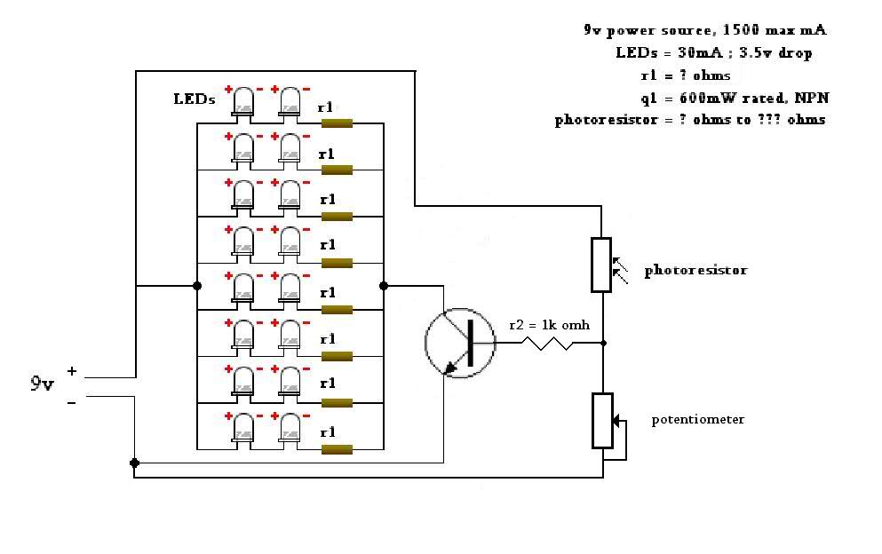
The photoresisor's resistance varies with the light intensity. You cannot physically adjust the resistance of the photoresistor aside from manually placing a foxed brightness light source in front of the photoresistor. It's not critical to know the range. They can be as little as 50 ohms with bright light and many MegOhms in darkness. The adjustable resistor however is used to pinpoint at what light level the LED's will turn on and is normally done by trial and error.Awesome, thanks a million.
I want the LEDs to increase in brightness when the photoresistor is hit with more light (light activated, I guess).
I'm assuming the potentiometer and LDR in the diagram are representative of 1 photoresistor? So then I just need to figure out the resistance range of the photoresistor and adjust my LED resistors accordingly?
For your application, LED's on when photoresistor sees increased light, you would use the third circuit provided. This would mean that one lead of the photoresistor is connected to the positive source, the other to buth the transistor base and variable resistor.Also, would one lead of the photoresistor be connected to the base of one NPN, and the other lead connected to the negative lead of the power source? I understand how to wire the LEDs, resistors, and transistors, just not the photoresistor.
Thanks again for everyone's help so far. Sorry I'm so newb at this.