At this point it is not clear as to just what the TS is looking for. To light the strip, apply 12 volts with the correct polarity.
Be advised, however, that 12 volts, unfiltered, from a bridge rectifier, results in a lot lower amount of power dissipated in those LEDs than with well filtered 12 volts DC.
ALSO: A WARNING if the power supply board only has diodes to change the AC to DC, then that board needs to be supplied with 12 volts AC, not 120 volts AC. Application of rectified mains power will cause almost instant total destruction of the LED string.
I guess what I am asking is what type of ic rectifier would rectify the ac to DC best and drive the LEDs at 415mA constant current, split among the branch?
As the ledstrip already has current limiting resistors, a stable 12 Volts powersupply would do.
There will be enough adapters that can provide 12 Volts at 1 A.
12V is a very likely guess because that is the typical voltage used for strips with 3 white LEDs in series.
The big advantage of 12V strips is the lower current, which means less voltage drop along the strip than 5V with single LEDs. You also need 1/3 the resistors of a 5V strip. 24V is even better, you could put 6 or 7 in series.
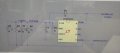
The circuit in post #29, as shown, will apply about 150volts DC directly across the diodes. That is due to that diode, "D1" shunting the regulator device. Didn't anybody else see that???
Again, does it matter where the resistor is? You did not answer that. It seems to me, you think the resistor must be between the power supply and the 3 LEDs. Is that true?
The circuit in post #29, as shown, will apply about 150volts DC directly across the diodes. That is due to that diode, "D1" shunting the regulator device. Didn't anybody else see that???
"7.3.4 Blocking Diode A blocking diode is required between the drain of the switch (DRAIN) and the anode of the LED stack.
This prevents the LED capacitor from discharging through the switch during the switch ON time instead allowing it to discharge through the LED stack.
This diode should be rated for 200 V reverse voltage and capable of forward currents as high as the average linear regulator current setting." How this chip should be used, in comparison with TS's circuit:
 Facebook
 Google
 GitHub
 Linkedin
") But didn't want to give it away!
But didn't want to give it away! 


