Facebook
 Google
 GitHub
 Linkedin
Hello all,
I am involved in one thesis task. I am using "FC300R-120" LED that has following characteristics:
Max. forward current= 100mA
forward voltage between 1.7v-2.3v
and Datarate of 250Mbps.
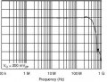
According to the specifications, the -3db optical power is achieved at 100MHz frequency at 20mA bias.
Now my task is to use any simple circuit (for example: RC circuit) added infront of LED to increase this -3db optical power achieved at 135MHz or 150MHz instead of 100MHz.
The curve should be linear.
As per specification the above mentioned 100MHz -3db curve looks like the 1st graph that I attached below.
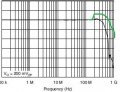
And now, I should make a lump at 100MHz using this "simple circuit" so that the -3db falls at later frequency range. (I ve drawn the approximated circuit and attached as 2nd image.
Can someone please help me/suggest me how to proceed with this?
I am involved in one thesis task. I am using "FC300R-120" LED that has following characteristics:
Max. forward current= 100mA
forward voltage between 1.7v-2.3v
and Datarate of 250Mbps.
According to the specifications, the -3db optical power is achieved at 100MHz frequency at 20mA bias.
Now my task is to use any simple circuit (for example: RC circuit) added infront of LED to increase this -3db optical power achieved at 135MHz or 150MHz instead of 100MHz.
The curve should be linear.
As per specification the above mentioned 100MHz -3db curve looks like the 1st graph that I attached below.
And now, I should make a lump at 100MHz using this "simple circuit" so that the -3db falls at later frequency range. (I ve drawn the approximated circuit and attached as 2nd image.
Can someone please help me/suggest me how to proceed with this?
Attachments
-
 26.6 KB Views: 14
 -
 35.6 KB Views: 10