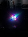
So I powered the fixture only from the 12v supply ignoring the DMX controller completley. in this configuration the red and the blue lights came on only, all RGB disconnected, when I touched the green negative with my fingers the green lights came on (wasnt expecting that) when I connected them all to ground all lights went off!Hopefully the result we WERE expecting
Sadly my hands aren't what they were after spinal surgery so I think its me that has damaged the mosfets although I was really careful. So if its resistor method could you kindly let me know what I need to do please, thanks in advance.
it depends on current draw of the LEDs.
DD311 is rated for 1A and i doubt that DMX controller can drive that kind of current directly.
so one can use own series resistor for LEDs and a mosfet as shown before:
in this case series value of resistor need to be determined.
of the LEDs are drawing I=300mA with Vf=3.2V forward drop, resistor will need to be determined using known supply voltage and number of LEDs per branch.
since supply is 12V, 3 LEDs would have a voltage drop of 3*Vf or 9.6V in this example. so 12V-9.6V = 2.4V across resistor.
and since branch current is same for the LEDs and resistor (they are all in series), dissipated heat would be:
0.3A * 2.4V = 7.2W (use larger value as safety margin, such as 10W). resistance would be 2.4V/0.3A=8 Ohm. More common value is 8.2 Ohm, so each Rext in this circuit would need to be 8.2 Ohm / 10W.
since you are not experienced, it would be a good idea to have some clamp of the mosfet gates to prevent ESD damage.
a simple protection could be a zener diode and series resistor.
some specs I do know the controller (512DMX box) is 3A x 24 channel, also the leds are 3w each which will be 3 to each RGB channel so will be using all 24 channels = 8 fixtures. the power supply is 12v 18a. Does this change anything at all? Thank you
if LEDs are 3W, each string will be consuming 9W or about 1A at 12V. since each channel can handle 3A, mosfets are not needed - just the current limiting resistor (that was the main function of DD311). the only thing i am not sure about is if the channels are switched on high or low side (almost certainly it is the low side).
don't theo the LED type so Vf can be anything though most likely it is in 2.5-3.6V range
using 3V as baseline, that is 9V on LEDs so series resistor would need to be about 3.3 Ohm and 5W
but as stated, your PSU is a limiting factor. you can use larger resistor value to limit max current, but will need to recalculate power rating.
Then that power supply should be fine.
Need to find out how much current each 3 LED color is drawing when fully ON.
To do this will need to connect just one of the modules up for testing.
I'll post how to do this shortly.
Here's the setup for testing the current draw of the Red LEDs.
The G and B wires will be connected to the Neg of the module which is connected to the Neg of the power supply. R wire not connected.
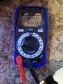
The meter will be set to read current using the 10A setting.
Dial set to the 10A position.
Black Common lead connects to the +12 volt wire on the module.
Red meter lead plugged into the 10A receptacle connects to the +12 volt terminal on the power supply. Take a photo of the complete setup and post for verification before turning on the power supply.
So sorry for the delay
First pic is fixture turned on
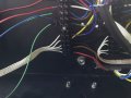
Sec is wiring
Third is with blue and green all connected to negative
Last pic meter set up
I'm ready to test leds
 Facebook
 Google
 GitHub
 Linkedin
")