So connect B G to neg, connect negative side of meter to imput on fixture and postive directly to 12 positive making sure meter is set to 10a and plugged in left side it that correct
So connect B G to neg, connect negative side of meter to imput on fixture and postive directly to 12 positive making sure meter is set to 10a and plugged in left side it that correct
Mostly sounds correct
Negative lead of meter to the +12 V power input on the module.
Red lead to the +12V output of the power supply.
Meter set for 10A
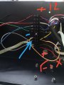
So top picture arrow is from 12v+ psu 12v+ positive meter goes here
Blue arrow B and G connected to neg - (showing red led when turned on) bottom arrow 12v from dmx box to fixture connect to black wire from meter.
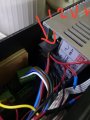
so wiring top down on choc block
1-6 is fixture 1
8-12 is Fixture 2
1.12v Red wire to PSU
2.Blue black Neg to PSU
3.white wire Blue DMX
4.Blue wire Green DMX
5.Brown Red DMX
6.Green Positive DMX
7.N/A
8.Blue Neg to PSU orange Neg to B
9.Yellow Blue DMX white loop B to G
10 Black Green DMX
11.Brown Red DMX
12.Positive from DMX
So the fixture at the monent goes to the DMX on connection 12 this has continuity back to the psu should I wire the fixture to the 12v only? Sorry this is a bit confusing
 Facebook
 Google
 GitHub
 Linkedin