LED Button Circuit Explanation

Thread Starter

cgw94

Joined Jun 11, 2020
42
This may seem a tad simple.

I am searching mouser for some parts and want to find an LED button that can monitor states.

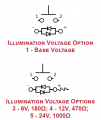
I found this one but I am not sure what the schematic is trying to show me.

for reference this is the schematic i am looking at.
1600695951579.png

I am currently using one that looks similar but both diodes go to a 0V/ground.


With this setup, it looks like i would have to connect one of those leads to ground meaning i would only be able to power one led and not both.

Am I reading this right?

Thanks!
 

Attachments

Tonyr1084

Joined Sep 24, 2015
7,852
Very poor diagrams and difficult to understand what it is you're trying to achieve. So I'll cover the basics for lighting an LED from a DC source. The same would apply to an AC source but there are some caveats.

Source voltage (minus) LED forward voltage.
Sum of that calculation divided by the desired current to be applied to the LED.
The dividend value is the resistor value.

Example:

12 VDC - 3.1 Vf = 8.9 V
8.9 V ÷ 0.02 A (20 mA) = 445 Ω

Vf is the forward voltage of the LED. They're all rated in Vf. They're also rated as a max current. Each color of LED, and each manufacturer will have a different Vf. "TYPICAL" Vf are for RED ~ 2 Vf whereas green, blue and white are typically around 3 Vf. Of the stock I currently have, the Vf's are as follows:
Red = 1.95
Yellow = 2.01
Green = 2.92
Blue = 2.82
White = 2.97
These numbers come from the average of measuring 10 out of 100 of each color. I also have RGB LED's (Red Green Blue). The measured Vf for each are 2.1 for red, 2.8 for green and 2.9 for blue. You can see from the foregoing list, comparing the green and blue numbers, they are reversed. So the numbers for each are critical. All my measurements were taken with a target starting voltage of 5 volts with 15 mA current. It's not an exact science, but it's a close enough ballpark to get a good and safe running LED.

As mentioned, AC is a little different. With high enough voltages, an LED, when reverse biased, can break down and burn out. So it's not uncommon to couple an LED with a diode to protect against reverse biased voltages. But now you're getting into a different realm.

The switch you have with two LED's - - - it would appear to me they gave you three light options: 1) Positive DC, 2) Negative DC, 3) AC. So no matter how it's hooked up - you should get some light. HOWEVER! They should have current limiting resistors. If you exceed the current for the LED it will burn up. Too much resistance and they will, depending on the actual resistance, barely glow or not even light up at all. So the schematic with the resistor and two LED's looks to be correct. However, the starting voltage is critical. If you buy an LED illuminated switch designed for 12 volts and use it on a 3 volt circuit; well lets look at the numbers: Assume a 12V 20mA with a Red LED switch: (12V - 2Vf) ÷ 0.02A = That should have a 500Ω resistor (as calculated). Use a standard 470Ω resistor to get fairly good brightness. But if that very switch is put on a 3 volt circuit: (3V - 2Vf) ÷ 0.02A = 50Ω. with the 470Ω resistor inside the switch, you'd have (3V - 2V) ÷ 470Ω = 0.002A (2 mA). You would be hard pressed to determine when it's lit and when not. But if you went the reverse with a switch designed for a 3V source and a 50Ω resistor and put it on a 12V circuit - - - you'd have (12V - 2Vf) ÷ 50Ω = 0.2A (200 mA) and a burned out LED.

If you need assistance, post a schematic (or a hand drawn idea) of what you're wanting to accomplish, we can help with guidance, advice and alternative approaches that may best resolve the problem you've encountered.
 

Thread Starter

cgw94

Joined Jun 11, 2020
42
Very poor diagrams and difficult to understand what it is you're trying to achieve. So I'll cover the basics for lighting an LED from a DC source. The same would apply to an AC source but there are some caveats.

Source voltage (minus) LED forward voltage.
Sum of that calculation divided by the desired current to be applied to the LED.
The dividend value is the resistor value.

Example:

12 VDC - 3.1 Vf = 8.9 V
8.9 V ÷ 0.02 A (20 mA) = 445 Ω

Vf is the forward voltage of the LED. They're all rated in Vf. They're also rated as a max current. Each color of LED, and each manufacturer will have a different Vf. "TYPICAL" Vf are for RED ~ 2 Vf whereas green, blue and white are typically around 3 Vf. Of the stock I currently have, the Vf's are as follows:
Red = 1.95
Yellow = 2.01
Green = 2.92
Blue = 2.82
White = 2.97
These numbers come from the average of measuring 10 out of 100 of each color. I also have RGB LED's (Red Green Blue). The measured Vf for each are 2.1 for red, 2.8 for green and 2.9 for blue. You can see from the foregoing list, comparing the green and blue numbers, they are reversed. So the numbers for each are critical. All my measurements were taken with a target starting voltage of 5 volts with 15 mA current. It's not an exact science, but it's a close enough ballpark to get a good and safe running LED.

As mentioned, AC is a little different. With high enough voltages, an LED, when reverse biased, can break down and burn out. So it's not uncommon to couple an LED with a diode to protect against reverse biased voltages. But now you're getting into a different realm.

The switch you have with two LED's - - - it would appear to me they gave you three light options: 1) Positive DC, 2) Negative DC, 3) AC. So no matter how it's hooked up - you should get some light. HOWEVER! They should have current limiting resistors. If you exceed the current for the LED it will burn up. Too much resistance and they will, depending on the actual resistance, barely glow or not even light up at all. So the schematic with the resistor and two LED's looks to be correct. However, the starting voltage is critical. If you buy an LED illuminated switch designed for 12 volts and use it on a 3 volt circuit; well lets look at the numbers: Assume a 12V 20mA with a Red LED switch: (12V - 2Vf) ÷ 0.02A = That should have a 500Ω resistor (as calculated). Use a standard 470Ω resistor to get fairly good brightness. But if that very switch is put on a 3 volt circuit: (3V - 2Vf) ÷ 0.02A = 50Ω. with the 470Ω resistor inside the switch, you'd have (3V - 2V) ÷ 470Ω = 0.002A (2 mA). You would be hard pressed to determine when it's lit and when not. But if you went the reverse with a switch designed for a 3V source and a 50Ω resistor and put it on a 12V circuit - - - you'd have (12V - 2Vf) ÷ 50Ω = 0.2A (200 mA) and a burned out LED.

If you need assistance, post a schematic (or a hand drawn idea) of what you're wanting to accomplish, we can help with guidance, advice and alternative approaches that may best resolve the problem you've encountered.
Thanks for all the info! I agree the schematic is not great. I just wanted to make sure i wasn't going crazy or missing something obvious.
 

dl324

Joined Mar 30, 2015
16,843
am currently using one that looks similar but both diodes go to a 0V/ground.

With this setup, it looks like i would have to connect one of those leads to ground meaning i would only be able to power one led and not both.
Switch and LED operate independently. What is your application?
 

Thread Starter

cgw94

Joined Jun 11, 2020
42
Switch and LED operate independently. What is your application?
It is for re-arming an alarm. Alarm armed, green, alarm needs to be armed, red. I can go for an option where they are separate but the upper brass thinks that it looks better together.
 

dl324

Joined Mar 30, 2015
16,843
It is for re-arming an alarm. Alarm armed, green, alarm needs to be armed, red. I can go for an option where they are separate but the upper brass thinks that it looks better together.
You can wire the LEDs however you want. To reverse polarity to the LEDs, you can't tie either terminal to ground (if you don't have a negative voltage available); you need to have a circuit that applies voltages of the correct polarity.

The referenced datasheet is pretty crappy. It gives LED color choices, but nothing about forward voltages and maximum currents; must be something where everyone just knows the specs.
 

Tonyr1084

Joined Sep 24, 2015
7,852
Here is one example of a "Bi-Colored" LED. I'm sure you don't need 100 pieces, but they're pretty cheap. This particular LED is "COMMON CATHODE". See the second slide. Also understand that the LED does not have a resistor applied in the component (inside the LED). You MUST use an external resistor. There's also a chart for Vf, which is probably specific to that particular LED. However, when dealing with Chinese made parts, often the data they provide is bogus. Nevertheless, with a little testing, and possibly sacrificing a few LED's, you can come up with a workable solution.
 

ElectricSpidey

Joined Dec 2, 2017
2,758
Pretty simple, just choose the red/green option, and use a small DPDT relay connected to the armed signal to select the colors.

Of course you might have to buffer the signal or choose to use an H-Bridge instead of a relay.
 

Tonyr1084

Joined Sep 24, 2015
7,852
Interesting followup to the Red/Green LED thing: I'm "Red/Green" deficient in my vision. I have a hard time telling red from green. Blue and Violet are also difficult for me to distinguish. Go figure how I made a 36 year profession as an electronics inspector. I can actually determine colors IF there's enough light AND enough "Color Area". In other words, a large section of a color is easier for me to detect than small and poorly lit colors. And with Blue and Violet - I have to study the blue to detect whether I can see a trace of red in the color. If it has red in the blue then it's violet. If not - it's just blue.

Hopefully the difference between the red and the green colors are sufficient because many a male are partially color blind. Few are nearly totally color blind. It explains why in nature (birds for instance) the male's are brightly colored to attract a mate; whereas the female's are much less colorful. Though this does not run 100% in the natural world it IS a common theme where a male (any species) needs to impress its female through visual cues. Color also plays a role in reproduction. And in the makeup industry as well. THAT's why women paint themselves, to attract attention.
 

dl324

Joined Mar 30, 2015
16,843
The LEDs can be driven with something like this:
clipimage.jpg
If you need more current, have the inverters drive some transistors and wire the LEDs accordingly.
 

Tonyr1084

Joined Sep 24, 2015
7,852
If you need more current
What voltage are we working with?

Those buffer inverters are good for low current applications. At 10V they can typically sink (ground) 16mA and source (supply) 3mA according to the Data Sheet.
1600703642172.png
 
Last edited:

Thread Starter

cgw94

Joined Jun 11, 2020
42
OP hasn't specified any parameters. LEDs as indicators typically don't need much current. Adding MOSFETs would make that a non-issue.
Lots of good info! Ya there is a lot of internal circuitry in a lot of these that help me manage the voltages. I was just mainly asking about that circuit and how to make it work. But the easiest solution is to get a new button! Thanks!
 
Top