Latch turns on automatically when using a battery

Thread Starter

jblake416

Joined Apr 9, 2026
11
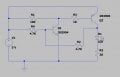
I've built the attached 2-transistor latch circuit, which functions perfectly when using a 5V (actually 4.76V in reality) breadboard compatible power supply (the ones that plug directly into the horizontal power rails on either edge, and are powered by either USB or a 9V plug). I'm using a momentary switch, which when pressed, the LED lights and the buzzer sounds, until power is disconnected, resetting the latch. I want to use a battery as power, however, when I switch to a 3.2V CR2032 the LED lights immediately upon connecting power, without pressing the switch. At first I thought it was a biasing issue, but in switching to 3 x AA batteries in series, which provided exactly 5V, it's thew same issue. Can anybody help me along with why this would happen? Any help would be appreciated.
 

Attachments

DickCappels

Joined Aug 21, 2008
10,661
Make your wires shorter. Even better is have a look at the latch output with a spectrum analyzer. Why are you using a 100 MHz (some versions 300 MHz) transistor to blink lights?
 

AnalogKid

Joined Aug 1, 2013
12,056
The output voltage of a power supply may seem to come up instantly, but it in fact ramps up over a few milliseconds. When connecting a battery by activating a switch, the voltage to the circuit comes up in microseconds. Ideally, the initial state of the circuit would be completely random. But because no two transistors are perfectly matched, that timing difference affects which transistor switches first.

Another possible reason - At startup, the current to turn on Q1 comes through 4.7K, while the current to turn on Q2 comes through 11K. So while both transistors are trying to come on, one has over twice the base current of the other. At any given point on the transistor transconductance curve, Q1 will have a lower impedance than Q2. The connection through R2 affects this, but not enough to matter.

To force the circuit to come up in the same state each time, add a small capacitor from either (not both) the base of a Q1 to Vcc, or the base of Q2 to GND. The small charging current will force that transistor to come on first.

ak
 
Last edited:

KeithWalker

Joined Jul 10, 2017
3,603
In your circuit diagram I don't see any way that Q1 can be biased off. Are you sure that R4 should be connected to the positive rail? It would make more sense to connect it to circuit common.
 

MisterBill2

Joined Jan 23, 2018
27,211
TRy using a different power supply than the tiny button cells. AND, more important, a higher voltage FOUR of the volt and a half batteries. AND, as others have mentioned, the circuit does not match the description. I see no pushbutton. I can GUESSthat it is between R4 and the battery positive. In that case it should indeed latch on when the button is pressed and the first transistor biased on.
 

Thread Starter

jblake416

Joined Apr 9, 2026
11
I’m not seeing the switch or the buzzer in your schematic?
Apologies for that. I couldn't find an SPST switch or buzzer in the LTSpice library, so I left them out, but neglected to mention that. My bad. I've added another type of switch for context (not sure exactly what it is in actual application). As for the buzzer, in my circuit it's in parallel to D1, but the circuit behaves the same way with or without it installed. Screenshot 2026-04-10 203841.jpgHere's the new schematic:
 

Thread Starter

jblake416

Joined Apr 9, 2026
11
Make your wires shorter. Even better is have a look at the latch output with a spectrum analyzer. Why are you using a 100 MHz (some versions 300 MHz) transistor to blink lights?
To be honest I just took the schematic from a tutorial video I found online, and used the components they were using...
 

Thread Starter

jblake416

Joined Apr 9, 2026
11
The output voltage of a power supply may seem to come up instantly, but it in fact ramps up over a few milliseconds. When connecting a battery by activating a switch, the voltage to the circuit comes up in microseconds. Ideally, the initial state of the circuit would be completely random. But because no two transistors are perfectly matched, that timing difference affects which transistor switches first.

Another possible reason - At startup, the current to turn on Q1 comes through 4.7K, while the current to turn on Q2 comes through 11K. So while both transistors are trying to come on, one has over twice the base current of the other. At any given point on the transistor transconductance curve, Q1 will have a lower impedance than Q2. The connection through R2 affects this, but not enough to matter.

To force the circuit to come up in the same state each time, add a small capacitor from either (not both) the base of a Q1 to Vcc, or the base of Q2 to GND. The small charging current will force that transistor to come on first.

ak
So here's my logic, please let me know where I'm going off the rails. Power is applied and the EB junction of Q2 is properly biased, but there is no path to gnd as Q1 has no EB current flow (yet), so there should be no current flowing across the EC junction of Q2. If I remove R2 however, the LED willl ight whenever I press the switch, and turn off when I release. Knowing this, I know that there is current coming through Q2 (EC junction), then through the 4.7K, and switching on Q1. How is this possible though?

Also, I added a 0.1 uF electrolytic capacitor to both Q1/Vcc and Q2/GND (individually of course), and in both instances the LED was just lit automatically. This happened with both the battery and PSU supplying power.
 

Thread Starter

jblake416

Joined Apr 9, 2026
11
In your circuit diagram I don't see any way that Q1 can be biased off. Are you sure that R4 should be connected to the positive rail? It would make more sense to connect it to circuit common.
With the emitter of Q1 tied directly to GND, wouldn't it have to have a positive voltage on the base to bias?
 

Thread Starter

jblake416

Joined Apr 9, 2026
11
TRy using a different power supply than the tiny button cells. AND, more important, a higher voltage FOUR of the volt and a half batteries. AND, as others have mentioned, the circuit does not match the description. I see no pushbutton. I can GUESSthat it is between R4 and the battery positive. In that case it should indeed latch on when the button is pressed and the first transistor biased on.
Yes exactly. Apologies for that, I neglected to mention it was missing the switch and buzzer. I've updated the schematic above. Also, same result with 4 x AA (6V) powering it.
 

KeithWalker

Joined Jul 10, 2017
3,603
When the switch is open, there is nothing to hold the base of Q1 low, so any electrical noise could trigger it. If you add an extra 4.7K resistor from the base of Q1 to circuit common, the bistable should work reliably.
 

Thread Starter

jblake416

Joined Apr 9, 2026
11
When the switch is open, there is nothing to hold the base of Q1 low, so any electrical noise could trigger it. If you add an extra 4.7K resistor from the base of Q1 to circuit common, the bistable should work reliably.
Thanks for the reply. So that seems to work intermittently. When I first tested with the new 4.7K in place it worked as desired for the initial button press, but when I disconnected power and reconnected the LED came on right away. In disconnecting and reconnecting a few times it seemed to be hit or miss as to whether it worked...
 

Thread Starter

jblake416

Joined Apr 9, 2026
11
I really appreciate all the replies. I guess what I'm trying to figure out here is why a battery would cause a different response than the power supply...
 

KeithWalker

Joined Jul 10, 2017
3,603
It is a bistable circuit. There is nothing in the circuit to determin its state when the power is applied. Add a 0.1uF capacitor across the new 4.7K resistor. That will keep the base of Q1 low long enough for the supply to settle down.
 
Maybe it’s just me being a bit thick but I can’t get my head around how and why your circuit should work. But I found this image with a quick search and, apart from the 3V supply which seems a bit low, I think I understand it.
1775899650547.png
In this case, when you briefly connect the “input voltage” (in your case the switch) BC547 turns on which pulls the base of BC557 low, which turns it on, lighting the LED and the voltage at the collector being greater than the LED voltage will hold the BC547 on. Maybe try this? The transistors you have should be okay and the resistor values should be according to this circuit. In your circuit I wonder about the resistor values, especially the 28R in series with the LED which is too low. Hope this helps
 

AnalogKid

Joined Aug 1, 2013
12,056
Yeah, in a 5 V circuit (post #1), you get around 100 mA for the LED current. That's high for a simple LED, but we don't know the designer's intent. Also, Q2 (the pnp) (Reference Designators - !) is acting as a saturated switch. Until you start to overcurrent the power supply, the value of Rled should have almost no affect on the collector voltage.

ak
 
Top