Facebook
 Google
 GitHub
 Linkedin
Hello! I have been given the opportunity to try designing a board for a 5VDC indicator/annunciator panel.
There are several control panels around a building with an on/off status contact each. When closed, a 24VDC signal is sent to this annunciator panel for that particular control panel.
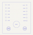
The annunciator panel has a red LED per connected panel, a buzzer, a momentary ‘test lamp’ button, and a momentary ‘silence’ button.
When a 24VDC signal is received by the annunciator panel, a corresponding LED should light up and the buzzer should energize. When the 24VDC signal turns off, the LED and buzzer should turn off too.
When pressing and holding the momentary ‘test lamp’ button, all of the LEDs should light up and buzzer sounds until the ‘test lamp’ button is released.
During normal operation, multiple lights could be on at the same time and the buzzer should remain energized as long as any light is on.
However, if an LED or multiple are on and the ‘silence’ button is pressed, the buzzer should turn off while the LEDs remain lit. If another LED turns on, the buzzer should re-energize until the ‘silence’ button is pressed again or the LEDs are turned off.
I do not have the components yet but have been working on trying this out in the Crumb simulator.
I haven’t learned LTSpice yet. The learning curve seems a bit steep, but I have it installed.
I do have components ordered to try it out for real on breadboards that should be here by next weekend. Eventually I hope to get PCBs made for this.
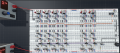
In Crumb, I have the LEDs and buzzer working with the 24VDC signals are on/off. The ‘test lamp’ button also works to turn on the LEDs.
The problem comes with the ‘silence’ button. I included a separate latching circuit per LED that should latch on when the LED is on and ‘silence’ is pressed. If I have only one of the latches connected to the button, it works as expected. If I have multiple latches connected in parallel, none of them will latch but they will silence the buzzer while the button is held down. I cannot tell why this is.
It is my understanding the mosfets work on the voltage, which should be the same across the parallel circuits.
I have not been able to find datasheet specs for the parts included in Crumb; there is only one mosfet that can be set to p-channel or n-channel, one BJT that can be set to NPN or PNP, etc. I am thinking the circuit may not be working because of the parts in Crumb.
For this annunciator panel, I am hoping for low current draw so I went with mosfets over BJTs. I would also like to avoid a micro controller or relays that make a clicking noise. In trying to latch the ‘silence’ button signal, I tried a thyristor in Crumb but it would fail to latch if there was ANY resistance downstream of it. With the mosfets, I could get it to actually latch with a single LED circuit where I couldn’t with the thyristor.
Since the mosfets are being used as switches, I consulted this page to try keeping n-channel and p-channel straight. I wasn’t entirely sure how you could use either if the mosfet is between loads; I think it would have something to do with biasing with resistors to keep the gate-source voltage above the Vgs(th) that I do not fully understand.
For the mosfet latching circuits, I am using copies of the last hard latch example in this thread.
I also had tried including a capacitor like they showed, but it did not appear to make a difference.
This thread has basically the same circuit, but only the momentary version where I am trying to use the hard latch.
There was this Reddit post asking about a latch that doesn’t work and were provided a link to this example that I admittedly haven’t tried but I’m not sure it would work for this.
Here is another thread I read, but the latches shown are momentary as well.
I am posting here for any guidance on how to get these parallel latches to work from a single button press, or affirmation if it should work just not with whatever the parts Crumb includes.
I am also interested if there are any glaring mistakes or ways I could make the circuits more robust.
Thank you for any help
There are several control panels around a building with an on/off status contact each. When closed, a 24VDC signal is sent to this annunciator panel for that particular control panel.
The annunciator panel has a red LED per connected panel, a buzzer, a momentary ‘test lamp’ button, and a momentary ‘silence’ button.
When a 24VDC signal is received by the annunciator panel, a corresponding LED should light up and the buzzer should energize. When the 24VDC signal turns off, the LED and buzzer should turn off too.
When pressing and holding the momentary ‘test lamp’ button, all of the LEDs should light up and buzzer sounds until the ‘test lamp’ button is released.
During normal operation, multiple lights could be on at the same time and the buzzer should remain energized as long as any light is on.
However, if an LED or multiple are on and the ‘silence’ button is pressed, the buzzer should turn off while the LEDs remain lit. If another LED turns on, the buzzer should re-energize until the ‘silence’ button is pressed again or the LEDs are turned off.
I do not have the components yet but have been working on trying this out in the Crumb simulator.
I haven’t learned LTSpice yet. The learning curve seems a bit steep, but I have it installed.
I do have components ordered to try it out for real on breadboards that should be here by next weekend. Eventually I hope to get PCBs made for this.
In Crumb, I have the LEDs and buzzer working with the 24VDC signals are on/off. The ‘test lamp’ button also works to turn on the LEDs.
The problem comes with the ‘silence’ button. I included a separate latching circuit per LED that should latch on when the LED is on and ‘silence’ is pressed. If I have only one of the latches connected to the button, it works as expected. If I have multiple latches connected in parallel, none of them will latch but they will silence the buzzer while the button is held down. I cannot tell why this is.
It is my understanding the mosfets work on the voltage, which should be the same across the parallel circuits.
I have not been able to find datasheet specs for the parts included in Crumb; there is only one mosfet that can be set to p-channel or n-channel, one BJT that can be set to NPN or PNP, etc. I am thinking the circuit may not be working because of the parts in Crumb.
For this annunciator panel, I am hoping for low current draw so I went with mosfets over BJTs. I would also like to avoid a micro controller or relays that make a clicking noise. In trying to latch the ‘silence’ button signal, I tried a thyristor in Crumb but it would fail to latch if there was ANY resistance downstream of it. With the mosfets, I could get it to actually latch with a single LED circuit where I couldn’t with the thyristor.
Since the mosfets are being used as switches, I consulted this page to try keeping n-channel and p-channel straight. I wasn’t entirely sure how you could use either if the mosfet is between loads; I think it would have something to do with biasing with resistors to keep the gate-source voltage above the Vgs(th) that I do not fully understand.
For the mosfet latching circuits, I am using copies of the last hard latch example in this thread.
I also had tried including a capacitor like they showed, but it did not appear to make a difference.
This thread has basically the same circuit, but only the momentary version where I am trying to use the hard latch.
There was this Reddit post asking about a latch that doesn’t work and were provided a link to this example that I admittedly haven’t tried but I’m not sure it would work for this.
Here is another thread I read, but the latches shown are momentary as well.
I am posting here for any guidance on how to get these parallel latches to work from a single button press, or affirmation if it should work just not with whatever the parts Crumb includes.
I am also interested if there are any glaring mistakes or ways I could make the circuits more robust.
Thank you for any help
Attachments
-
100 KB Views: 22
-
 2.1 MB Views: 17