 Facebook
 Google
 GitHub
 Linkedin
Posting in Rf forum only because ferrite rings are used quite a bit in various applications where Rf is involved.
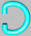
I am looking for a US supplier/seller for a ferrite D ring that looks like this one. It's gonna be fairly large, diameter of ferrite 3/4 to 1", and 4-5" across.
If I can't buy it as cots then I will investigate making it myself. It could be a solid D and I can cut out the opening.
I am looking for a US supplier/seller for a ferrite D ring that looks like this one. It's gonna be fairly large, diameter of ferrite 3/4 to 1", and 4-5" across.
If I can't buy it as cots then I will investigate making it myself. It could be a solid D and I can cut out the opening.
Attachments
-
 84.2 KB Views: 1


