Facebook
 Google
 GitHub
 Linkedin
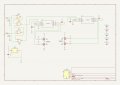
I recently purchased a H-bridge board that uses ST L6384d driver chips to drive 4 N mosfets. The input to the driver (pin 1) comes from a dual input NOR gate and the DT (pin3) is pulled low thru a 270k resistor. The gate has a Direction and PWM input. I have tested the board and it functions as advertised, feeding a square wave to the PWM pin and controlling motor direction with the other pin. Both inputs to the board are inverted so the only time the NOR gate outputs a high is when both inputs are high. I would think that when the Direction pin is high the output to the L6384d would be the PWM signal. Why wouldn't this cause the output of the L6384d to change at a PWM rate? Note: The other side of the H-bridge is an identical circuit but the NOR gate output is inverted. Could someone Please explain the operation of this drive IC? The circuit is wired up like the diagram on ST's data sheet with the addition of the 74hc02 NOR gates.
L6384 H-Bridge drive funcion.
- Thread starter bdrmachine
- Start date
-
- Tags
- half bridge l6384