L298N Motor Module with Arduino Mega doesn't work.

MrChips

Joined Oct 2, 2009
34,850
Is this your setup?
We cannot diagnose someone else's hardware. We must see your board.
There are three jumpers on a typical L298 board that ought to be in place.
We want to see how your batteries are installed.
 

ebeowulf17

Joined Aug 12, 2014
3,307
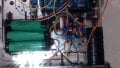
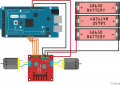
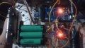
The wires are scrambled up, but I copied it from the video on
https://howtomechatronics.com/tutor...dc-motor-control-tutorial-l298n-pwm-h-bridge/
The ENA and ENB though are still not connected to the Mega board.
My understanding is that the enable pins don't have to connect to the Mega board since you don't want speed control, but they do have to connect to SOMETHING!

I can't see much in your blurry picture, but if the original layout sketch is accurate, there are 5V pins immediately beside each of the enable pins. Use jumpers (or short lengths of wire, or whatever) to tie each enable pin to a 5V pin.
 

AlbertHall

Joined Jun 4, 2014
12,628
In the picture of the motor driver below there are three jumpers fitted, motor enable A, Motor Enable B, and the 12V jumper. If your board is like this, those three jumpers should be fitted.
1581123419741.png
 

dendad

Joined Feb 20, 2016
4,641
The attachment shows my current updated setup.
This is still showing the enables not connected.!!!!!!
You can connect the enable pins to an Arduino port and drive them as required. Or just put the jumpers on and than the drivers are enabled all the time.
As you have them shown, it will not work as the motors are disabled.
How many times do you need to be told that?
 

Thread Starter

Ravdev

Joined Feb 7, 2020
18
This is still showing the enables not connected.!!!!!!
You can connect the enable pins to an Arduino port and drive them as required. Or just put the jumpers on and than the drivers are enabled all the time.
As you have them shown, it will not work as the motors are disabled.
How many times do you need to be told that?
I've connect them to PWM pins and rewrite the code but the DC motor still doesn't rotate. Should I make the 2 pins 5V in the code?
 

MrChips

Joined Oct 2, 2009
34,850
30 posts and 12 hours later, we could have told you a lot sooner how to fix your problem had you posted photos of what you have done!
 

Thread Starter

Ravdev

Joined Feb 7, 2020
18
Do you have jumpers Enable A and Enable B in place?
Do you have 12V Jumper in place?

View attachment 198569
The 12V Jumper has a jumper cap on it, while the ENA and ENB are connected to a PWM pin in the Arduino Mega.

Code:

const int IN_1 = 7;
const int IN_2 = 6;
const int IN_3 = 5;
const int IN_4 = 4;
int EN_A = 8;
int EN_B = 9;

void setup() {
// put your setup code here, to run once:
pinMode(IN_1, OUTPUT);
pinMode(IN_2, OUTPUT);
pinMode(IN_3, OUTPUT);
pinMode(IN_4, OUTPUT);
pinMode(EN_A, OUTPUT);
pinMode(EN_B, OUTPUT);
}

void loop() {
// put your main code here, to run repeatedly:
digitalWrite(IN_1, HIGH);
digitalWrite(IN_2, HIGH);
digitalWrite(IN_3, HIGH);
digitalWrite(IN_4, HIGH);
digitalWrite(EN_A, HIGH);
digitalWrite(EN_B, HIGH);
}
 

Thread Starter

Ravdev

Joined Feb 7, 2020
18
Also, have you posted your code?
Code:

const int IN_1 = 7;
const int IN_2 = 6;
const int IN_3 = 5;
const int IN_4 = 4;
int EN_A = 8;
int EN_B = 9;

void setup() {
// put your setup code here, to run once:
pinMode(IN_1, OUTPUT);
pinMode(IN_2, OUTPUT);
pinMode(IN_3, OUTPUT);
pinMode(IN_4, OUTPUT);
pinMode(EN_A, OUTPUT);
pinMode(EN_B, OUTPUT);
}

void loop() {
// put your main code here, to run repeatedly:
digitalWrite(IN_1, HIGH);
digitalWrite(IN_2, HIGH);
digitalWrite(IN_3, HIGH);
digitalWrite(IN_4, HIGH);
digitalWrite(EN_A, HIGH);
digitalWrite(EN_B, HIGH);
}
 

MrChips

Joined Oct 2, 2009
34,850
Scrap the PWM. Scrap the Arduino.

Put a jumper in Enable A and and jumper in Enable B.
Which side is the motor connected, Motor A or Motor B?

For Motor A, connect Input 1 to +5V, Input 2 to GND. Or the other way around.
For Motor B, connect Input 3 to +5V, Input 4 to GND. Or the other way around.

Your motor should turn if your wiring is correct.
 

Thread Starter

Ravdev

Joined Feb 7, 2020
18
Scrap the PWM. Scrap the Arduino.

Put a jumper in Enable A and and jumper in Enable B.
Which side is the motor connected, Motor A or Motor B?

For Motor A, connect Input 1 to +5V, Input 2 to GND. Or the other way around.
For Motor B, connect Input 3 to +5V, Input 4 to GND. Or the other way around.

Your motor should turn if your wiring is correct.
If I directly connect the IN1, IN2, IN3, and IN4 to the 5V and GND of the Arduino it rotates, but if I put it in the pins and upload the code, it seems like it doesn't read anything and doesn't rotate.
 

MrChips

Joined Oct 2, 2009
34,850
So the problem is with the Arduino.
Leave the Enable A and Enable B in place.

Use this code:

digitalWrite(IN_1, HIGH);
digitalWrite(IN_2, LOW);
digitalWrite(IN_3, HIGH);
digitalWrite(IN_4, LOW);
 

dendad

Joined Feb 20, 2016
4,641
Try this in a loop...


digitalWrite(IN1, LOW);
digitalWrite(IN2, HIGH);
digitalWrite(EN_A, HIGH);
delay(1000);
digitalWrite(EN_A, LOW);
delay(1000);
digitalWrite(IN1, HIGH);
digitalWrite(IN2, LOW);
digitalWrite(EN_A, HIGH);
delay(1000);
digitalWrite(EN_A, LOW);
delay(1000);

Arrrr!
@MrChips beat me :)
 
Top