 Facebook
 Google
 GitHub
 Linkedin
Hello all,
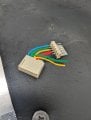
I currently have a connection that uses a KF2510 connector. I don't want to modify either end of the connection, but would like to add something in between in order to get to the ground wire and two of the remaining 4 wires that are part of the 6 pin connector. One port does not contain a wire.
Hopefully the crude picture and diagram will help to clarify my explanation.
I can easily take the new female connector pictured on the left and add new wires, and include multiple wires coming out of three of the slots where I require them. The challenge for me lies in how I can male connector to the wires that I have drawn, without using a printed circuit board. I've looked for some type of adapter, but have had no luck finding such a thing. I'd like to avoid the circuit board as I'd like to make quite a few of these and would like to avoid the additional bulk of the board and potential fragility due to my sub-part soldering skills.
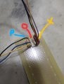
I've also attached what I have for a working prototype, with the input cable from the original device (Red "O") disconnected and not in the picture. The output would still go to the original device via the Yellow "X" and the alternate signals would flow through the Blue "P".
Thanks for taking the time to read through my post and any advice is greatly appreciated.
Darryl
I currently have a connection that uses a KF2510 connector. I don't want to modify either end of the connection, but would like to add something in between in order to get to the ground wire and two of the remaining 4 wires that are part of the 6 pin connector. One port does not contain a wire.
Hopefully the crude picture and diagram will help to clarify my explanation.
I can easily take the new female connector pictured on the left and add new wires, and include multiple wires coming out of three of the slots where I require them. The challenge for me lies in how I can male connector to the wires that I have drawn, without using a printed circuit board. I've looked for some type of adapter, but have had no luck finding such a thing. I'd like to avoid the circuit board as I'd like to make quite a few of these and would like to avoid the additional bulk of the board and potential fragility due to my sub-part soldering skills.
I've also attached what I have for a working prototype, with the input cable from the original device (Red "O") disconnected and not in the picture. The output would still go to the original device via the Yellow "X" and the alternate signals would flow through the Blue "P".
Thanks for taking the time to read through my post and any advice is greatly appreciated.
Darryl
Attachments
-
 1.7 MB Views: 7
 -
 1.2 MB Views: 7


