Just some general questions about remaking something from the past

Status
Not open for further replies.

Thread Starter

Berzerker

Joined Jul 29, 2018
623
It's not an enclosure AG it's a cover. Just a plastic heat proof cover. All it covers is the amp on the bottom and the heatsink for safety.
And yes AG it will have vent holes in it "a lot of them". And boomy bass is what everyone wants. You don't have people where you live running around with their cars vibrating the pavement ?
 

Audioguru

Joined Dec 20, 2007
11,248
Deep, very low frequencies vibrate things and can be felt. Most people want sound systems that do that. Boomy upper bass has no deep low frequencies and produces "one-note-bass" like a bongo drum that produces no deep low frequency bass. Some dumb teens like that.

Some people do not know anything about speakers and their sounds are bad. Most people have properly designed speaker systems and they sound very good.
 

Thread Starter

Berzerker

Joined Jul 29, 2018
623
shortbus said:
Why do you always go to extremes? Or were you just messing with me over my suggestion?
You'd just have to met me in real life shortbus. I'm and outgoing person with a crazy attitude. I love God, my family, Life and my country.
pretty much in that order. why do you think I picked the name Berzerker?.
No I actually like the Idea very much AND I changed my design this morning around the IC because of your suggestion about the power being to close to the other signal wires and made my traces wider. Thank you very much. Now I'm in the process of making sure it will fit around the speaker "without looking awful". I'm not messing with you shortbus and again "I appreciate your help".
 

shortbus

Joined Sep 30, 2009
10,049
Guess we are pretty much the same. I know I have a weird sense of humor and people sometimes take my way of saying things wrong. But came from over 50 years of having to get things right the first time and in the fastest time. Like you, was a machinist/die maker.
 

ebeowulf17

Joined Aug 12, 2014
3,307
Totally off-topic, but as long as I've got two machinists in one thread, I have a question for you regarding tolerances.

In all my past experiences, tolerances were explicitly called out. You might have something be 20mm +/- 0.5mm, or 20mm +0.5/-0.2. I've seen lots of global tolerances where the title block includes something like "all tolerances +/-0.5mm except where otherwise noted."

Right now I've got a co-worker who believes tolerances are implied by the precision of your stated dimension (the number of decimal places in most cases.) For example, a 20.0mm piece has a tighter tolerance than a 20mm piece, and a 20.00mm piece has even tighter tolerances than the 20.0mm piece.

Does this ring true for you guys? It seems silly, imprecise, and unenforceable to me, but I have limited experience with such things, and I know different industries handle things differently, so maybe this is just my first exposure to a well known system. Have you encountered anything like this before?
 

Thread Starter

Berzerker

Joined Jul 29, 2018
623
Tolerances are specified or "noted". There is no universal if you place this number here and it has 20 (zeros) behind it gets this tolerance. Tolerances are given to make the hole or pattern as loose or as tight as you need. one might place a tolerance of .0005 to .001 smaller for a press fit or even +.005 for a slip fit. I've seen tolerances up to + or - .020. Most of the time you drill a hole for a 1/2" bolt something like 9/16" cause you don't want to beat it in you just need enough clearance for it to slip through.

And don't worry about going off topic ebeowulf. You wanted to ask a question and you got one persons opinion on it. All drawings I've ever been around told you what the tolerances were.
Edit: Or at least that's how I was taught to make drawings.
 
Last edited:

shortbus

Joined Sep 30, 2009
10,049
And I learned completely different than Berzerker. In my area ,it is the number of zeros after the decimal point that calls the tolerance. The title block is something from back in the day, and on most CAD generated drawings today isn't even included.
 

Thread Starter

Berzerker

Joined Jul 29, 2018
623
Yea it's been a while since I've been around doing Cad. yes I learned with title blocks. Just the way I was taught at the company where I worked.
Maybe I stated what I said was a little incorrect. ebeowulf used the example
ebeowulf said:
For example, a 20.0mm piece has a tighter tolerance than a 20mm piece, and a 20.00mm piece has even tighter tolerances than the 20.0mm piece.
To me there is no difference in 20mm and 20.0mm. The .0 in the decimal is of no value at this point. That to me is different than placing (2.002 - 2.005) in a drawing. <--- This specifies a tolerance.
I guess it was the way he asked it.
 

ebeowulf17

Joined Aug 12, 2014
3,307
And I learned completely different than Berzerker. In my area ,it is the number of zeros after the decimal point that calls the tolerance. The title block is something from back in the day, and on most CAD generated drawings today isn't even included.
Interesting. So in that system, what are the resulting tolerances? Is it just any value that rounds to the specified value? So 20.5 would allow for basically 20.45 to 20.55, but 20.50 would only allow for 20.495 to 20.505. Something along those lines?

If you don't mind my asking, what part of the world do you live in, and did you specialize in any particular industry? (marine, automotive, aerospace, etc.) I'm wondering if this is a regional difference or an industrial application difference.
 

Thread Starter

Berzerker

Joined Jul 29, 2018
623
To me if you specify drill .500 you put in a 1/2" drill and drill. The tolerance is whatever the drill, drills the hole. No hole is totally perfect. for tighter tolerances you would bore, ream, turn....etc. My point of view is if it says 2.002- 2.0025, you have one half a thousands tolerance.
 

shortbus

Joined Sep 30, 2009
10,049
To me if you specify drill .500 you put in a 1/2" drill and drill.
See again we differ. When a no tolerance hole is needed it would be shown as 1/2" diameter. A 0.500 would be a reamed or bored hole. We had one new engineer that sent out work for bids and couldn't understand why all of his jobs came in so high and couldn't be afforded to be made. When I looked at the prints he was sending out it was very obvious why, all of his dimensions were four or more places even his clearance holes. Many because of the zeros he thought meant nothing.

Interesting. So in that system, what are the resulting tolerances? Is it just any value that rounds to the specified value? So 20.5 would allow for basically 20.45 to 20.55, but 20.50 would only allow for 20.495 to 20.505. Something along those lines?
Here is a quick read that looks like how I was taught and worked. https://www.machinedesign.com/materials/working-dimensional-tolerances

If you don't mind my asking, what part of the world do you live in, and did you specialize in any particular industry? (marine, automotive, aerospace, etc.) I'm wondering if this is a regional difference or an industrial application difference.
I live and worked in the northeastern part of Ohio. I worked many places on many types of things. Automotive parts, both dies and plastic molds. Areospace and prototype military work for a few different companies. Some work for a company on nuclear reactor parts and test samples on materials going into reactor making. Built on many different kinds of production machinery for different type of manufacturers. Made gauges to check many different kinds of things and fixtures for welding and holding parts for machining. Plus the stuff I did for my self in building cars and motorcycles mostly from scratch.
 

Thread Starter

Berzerker

Joined Jul 29, 2018
623
I have seen drawings with all kinds of ways of dimensioning on them. title blocks, line leaders, etc. I think I could have summed it up better if I said it's up to the person that makes the drawing. I was taught to do what a print says? If it says drill "you drill" If it says ream "you ream".
Just so everyone knows I've never been to a drafting class in my life. I taught myself Cad and 3D design. The drawings I produced for the company I worked for were mostly took from my boss's layouts which had to be corrected much of the time. As shortbus stated you catch all kinds of mistakes on prints all the time. And I also said I was in the sawmill business so the tolerances were not as demanding as what shortbus has to deal with. most of the time our tolerances were + or - .001 or .002 except for bearing fits. But the parts were often very large or long. And I don't think a tree (cant) is what their called would notice a couple of thousands difference. without calipers or mics no one would. There wasn't a CNC nowhere in our shop (all manual). Big and old machines to produce a massive quantity of parts. One machine we made a "canter" was over 60 ft. long, 12 ft. wide and 15 ft. tall. The closest we came to tight tolerances were on the surface grinder + or - .0002. "It was an old 2' x 48" surface grinder" To this day the surface grinder is still my favorite machine.
 

ebeowulf17

Joined Aug 12, 2014
3,307
Awesome! Thank you both for your perspectives. It's very interesting seeing how differently things can be handled. I've seen this in many other fields, but until very recently l thought there was more standardization in mechanical drafting standards than there apparently is. I've taken some drafting classes and worked with drawings intermittently throughout my career, but in my limited experience I'd never run into implied tolerances before.

I'll be a little more patient with my co-workers now that I know their version of implied tolerances has some basis in existing industry practice. I really thought they had just made it up based on intuition, wishes, and the desire to not spend time defining tolerances.

My personal preference would still be to explicitly call out tolerances, whether in global notes, individual callouts, or a combination of the two, but it's nice to know my co-workers aren't crazy on this one!
 

Thread Starter

Berzerker

Joined Jul 29, 2018
623
ebeowulf said:
My personal preference would still be to explicitly call out tolerances, whether in global notes, individual callouts, or a combination of the two, but it's nice to know my co-workers aren't crazy on this one!
That's how I look at it. then there is no mistake about what you should do.

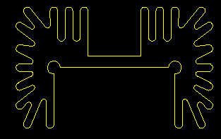
Edit: here is a pic of the heatsink I made for my layout. Is it correct? Heck I don't know but the inside and outside dimensions are correct. If you seen this on a print you'd know what is was. I don't have one in hand to make it to exact size.
 
Last edited:

ebeowulf17

Joined Aug 12, 2014
3,307
That's how I look at it. then there is no mistake about what you should do.

Edit: here is a pic of the heatsink I made for my layout. Is it correct? Heck I don't know but the inside and outside dimensions are correct. If you seen this on a print you'd know what is was. I don't have one in hand to make it to exact size.
Looks beautiful!

Though, if I'm totally honest, it's overkill. All you really need is an outline to make it obvious that other parts can't encroach into that space, and any mounting holes it requires, and maybe something to indicate orientation if the outline and mounting holes don't make it obvious.

As I said before, my approach was to make a combined part that included the component and the heatsink all in one. That way, l couldn't possibly move one and forget to move the other.

Regardless of my preferences, your heat sink looks good from here. Does it need mounting holes, or does it only attach to the device it's cooling? If it needs holes, add them - otherwise I think you're good.
 

Thread Starter

Berzerker

Joined Jul 29, 2018
623
This is in AutoCad and I was also taught you make it as close as you can to real life. If it says .010 you make it .010. I will correct it when I get one in my hands. To me a square with circles for holes in a drawing could be anything. I placed a square outline with the hole pattern in diptrace just like I would use a block such as the one above in a Cad drawing. I didn't go through all the trouble of correcting the IC to show the heatsink in diptrace. After learning you either have to go with the what's on the silk or not there is no removing certain parts of it and leaving others, I didn't want the outline on the PCB.
 

shortbus

Joined Sep 30, 2009
10,049
I've seen this in many other fields, but until very recently l thought there was more standardization in mechanical drafting standards than there apparently is.
It really was in earlier days, like when I was in school. But like many things, cursive writing for instance, it has gone or is going the way of the Dodo. And I hope to be pushing up daisies before it gets too much worse. Computer related things are great but much has been lost to them, and old fossils like me resent much of it.
 

Thread Starter

Berzerker

Joined Jul 29, 2018
623
I remember a long time ago a guy came to our shop and was helping me with one of their products in our database. We got talking about printing. I asked a simple question about how he done scale on a drawing. I heard the most outrageous thing about printing is like cutting a hole in a print and putting it on another piece of paper. He went through a bunch of un-necessary steps to achieve the out come. Then he asked how I done it and I said I just pick the objects in the select window, go to file print, it asks me to select a border for the display, window what ever I want. pick a scale and hit enter and then print. Worked just fine, 3 times as quick and printed the exact same thing.
 

Thread Starter

Berzerker

Joined Jul 29, 2018
623
Bought the 2 Ohm 3 way speakers from Crutchfield yesterday, the components from Digikey, step -up and step-down converters, four wire connectors for inputs and power and a few other things I thought I would need to check dimensions.
 
Status
Not open for further replies.
Top