Just some general questions about remaking something from the past

Status
Not open for further replies.

Audioguru

Joined Dec 20, 2007
11,248
Transformers, Watts,Volts and amps?
The Darlington transistors in the MindBlower speaker are emitter-followers that have no voltage gain. They use a low input current and produce a fairly high output current. The transformers increase the signal voltage.
When the output voltage across a resistor or a speaker is increased then its current requirement also increases according to Ohm's Law.
 

Thread Starter

Berzerker

Joined Jul 29, 2018
623
AG said:
When you turn down the volume control on the radio then don't you think it reduces the power going into the Mindblower speaker??
As you said now radios have more power, amps and watts from the factory. I also know they have low and high level inputs on some amplifiers. you would not hook a 40 watt (10 per channel) radio into a amplifier unless you hook it up to the high level inputs. Radios are totally different now than then. and yes the volume knob does turn it up and down but, you are not pushing 10 watts at 2 on that knob if the knob goes to 10.
 

Audioguru

Joined Dec 20, 2007
11,248
The MindBlower speaker did not have a "low level" input. Its input was the speaker output of an old car radio.
They say its maximum input is 10W because a higher power might blow up a Mindblower speaker.

Don't you know that our hearing's sensitivity to loudness and volume controls are logarithmic causing 10 times the power sounds only twice as loud and double the power is just a little louder? Turning down a volume control from max to halfway cuts the voltage level to 32% which produces 1/10th the max power, but usually the volume control probably has some "headroom" so you can turn up faint sounds. Maybe the knob set to 7 out of 10 is the maximum normal output voltage then halfway produces 50% which is 1/4 the maximum power.
 

Thread Starter

Berzerker

Joined Jul 29, 2018
623
I was talking about a difference in what I would do now and what was back then. More watts cos 30-50 won't attract many people nowadays. different set up, maybe I can add low and high level inputs I don't know (yet). once I learn how this one worked and amplifiers in general I will move on and design my own. This is so simple of a design "again wish I knew what you do" that it was genius. you asked one time wonder why they went out of business? It could have been he died or a company fallout or any number of reasons, (NOT) that it was bad.
 

Audioguru

Joined Dec 20, 2007
11,248
Today people buy Name Brand amplifiers and speakers. The Tenna MindBlower went out of business probably because the custom-made transformer and custom-made speaker were very expensive. The amplifier had no negative feedback then its distortion was fairly high and the transformers cut lows and highs.

If you designed and made a modern high power amplifier and speaker then can you compete with the Name Brand companies?
 

Thread Starter

Berzerker

Joined Jul 29, 2018
623
Got several tabs open on my computer now AG one on this sites tutorials, one on the forums and one or two on google. I know you do audio AG I can tell from how you respond to my posts. And I know about amps. how to hook them up, inputs - outputs, so called wattage when we all know it's not correct. I have a pile 4 channel 2000 watt amp and a dual car radio w/ flip out display still in the box sitting in my room At the time I had two cars one for work, one for play. the car I sold so then I only had my SUV for work. I never installed it because I didn't want it in my work truck. I also have in box a 15" DVD player which I'm still waiting to install but not in a work truck. Installing one and designing are two different things.
Edit; here where I'm at we call a truck and a SUV "a truck". And I'm semi-retired now.
 
Last edited:

shortbus

Joined Sep 30, 2009
10,049
once I learn how this one worked and amplifiers in general I will move on and design my own.
This is why I sent you to the audio sites. Just because most of it was based on home audio, a car audio system works on the same principles.

And from one that was once in your situation, if you think this can be done in a few posts, or the reading of a few web pages, good luck with that. I had a small knowledge of electronics before trying to learn more, built several Heathkits and things from the magazines. But when it comes to actually figuring out how to make an idea into a working thing, well I've been doing it for ~15 years now, and am just now getting my idea so it 'might' work. But then again that's just me, you may be totally different.
 

Thread Starter

Berzerker

Joined Jul 29, 2018
623
I didn't think it would be easy shortbus. In fact it's more harder than I expected though. Last couple of nights I've even dreamed about electrical circuits and failing at it. Pretty bad huh? I never thought it would be over night and "here you go" here's your amplifier. As in the few posts before; the current, voltage, watts, amps, and the calculations you have to know to get the answers you need is a bit overwhelming. It isn't like poking in the sine and cosine in a calculator and here's your bolt hole pattern in machining. But for only being at it for 15 days now I have learned what transistors diodes, capacitors, resistors do "kinda" :) I've found out there are two different voltages on it AC and DC. I took it for granted that if it's hooked up to DC the output must be DC, forgetting what a transformer is for and not knowing that radio speaker output is AC. The fact that having a teacher would make it much more easier. But I pretty much taught myself Autocad and 3D modeling and knowing it didn't happen over night and the times I didn't understand and wanted to give up puts a charge in me to push on. I can tell it's going to be rough.
 

Thread Starter

Berzerker

Joined Jul 29, 2018
623
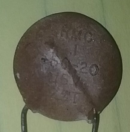
Ok I took a little break from al the numbers and calculations. My brain needs a rest.so I started looking at parts again. I went back to the capacitor I said was obsolete and reading more on this. found this on google:
google said:
The letter Z donates a tolerance of +80 percent and –20 percent. That means the capacitor, which is rated at .1 μF, might be as much as 80 percent higher or 20 percent lower.
Ok it's a 1uf "I think" +60 -20 15v capacitor? from what I'm reading I "CAN" use a higher voltage capacitor like 20v, 25v, or even 30v this is only the voltage it will store before failure (correct)? The percentage + or - is just the higher or lower voltage it might incur (correct)? So the 1uf is the main thing to look for (correct)? Now it's really hard to tell if there is a (DOT) before the 1 in 1uf "0.1uf" because of how old and faint it is I know it matters a lot not going there. let's say I can find one with +80% or a +100% or only with -10% will this cause failure? What if I'm searching for a 1uf and it's a 0.1uf and that's why I said I couldn't find one? here's a pic of it?

Now that I posted it and looked closer I think it says .1uf. Ok I went back before hitting edit reply and checked? still no .1uf at any voltage, No 1uf at any voltage? "At any + or - percent" There has got to be something close or no none would ever be able to make anything.
 

shortbus

Joined Sep 30, 2009
10,049
calculations you have to know to get the answers you need is a bit overwhelming.
The math is my big sticking point. Just barely got by in algebra 55 years ago and haven't gotten any better since. Trig for the things needed to figure angles and measuring them I did get better over the years, but like many things in life, if you don't use it you lose it.

And to the cap you need to learn that tolerance in electronics isn't like in machining. The value of that cap can somewhat be "guessed" at by looking at data sheets, the outside diameter in particular. Volt of the cap is another thing, when you know what the circuit voltage is you just pick a value that is around at least 1.5 times the circuit voltage. Going higher on the voltage won't hurt as much as going lower. Anything in electronics needs to be over rated for working voltages of the circuit. Or the chances are good you will see smoke, and it won't be from the Indians talking long distance.:)
 

Thread Starter

Berzerker

Joined Jul 29, 2018
623
Point taken shortbus. But I went on digikey and just started poking in voltages, uf's', through hole, ceramic, this kind, that kind...etc. and it kept popping up nothing? Not one? I mean there has to be one somewhere that is kinda close. how would anyone ever design or repair something without different values. I even put in aluminum electrolytic and still nothing. you can use a different type as long as it has the correct values (right).
 

ebeowulf17

Joined Aug 12, 2014
3,307
Point taken shortbus. But I went on digikey and just started poking in voltages, uf's', through hole, ceramic, this kind, that kind...etc. and it kept popping up nothing? Not one? I mean there has to be one somewhere that is kinda close. how would anyone ever design or repair something without different values. I even put in aluminum electrolytic and still nothing. you can use a different type as long as it has the correct values (right).
I've got over 1200 hits for 0.1uF ceramic through hole caps rated for at least 30V.

https://www.digikey.com/products/en...14=22&pv14=32&pv14=38&pv14=111&pv14=2&pv69=80

I may have forgotten some parameters. What other parameters are you using? Are you sure all the specs you've put in matter?

Also, be aware that a lot of selections in the DigiKey and Mouser filters require massive amounts of multi-selecting. For example, if you choose to limit your search to caps that can handle 10V, DigiKey will show you only caps whose upper limit is exactly 10V. If you want all caps that can handle at least 10V, you have to select every value from 10V on up individually.
 

Thread Starter

Berzerker

Joined Jul 29, 2018
623
I clicked on your link ebeowulf and got:
"Make sure all keywords or part numbers are entered correctly."
I entered all kind of volts as I said. Both .1 and 1uf.
AG said:
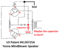
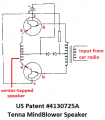
The schematic in the patent does not show a capacitor. What was yours connected to? Please sketch it on the patent schematic I am posting:
look at post #105 and #140, it's on the GRN side.
 

ebeowulf17

Joined Aug 12, 2014
3,307
I clicked on your link ebeowulf and got:
"Make sure all keywords or part numbers are entered correctly."
I entered all kind of volts as I said. Both .1 and 1uf.
look at post #105 and #140, it's on the GRN side.
Like l said, there are thousands to choose from, so something else must be going on.

Try using fewer search terms. Don't specify voltage, tolerances, or anything else right off the bat. Just start with ceramic caps. There should be tens or hundreds of thousands. Then try adding the 0.1uF filter. Refine the list down in baby steps until you have a small list to choose from. If you're ending up with zero, something has gone wrong.
 

Thread Starter

Berzerker

Joined Jul 29, 2018
623
That worked ebeowulf I guess you can't just pick them all at once and go. found a 25v .1uf thousands in stock. Now I will try to get closer like 16V and check some at 1uf. I thought you just picked what you wanted and it would take you there. wish I could tell what it was exactly. See what you think of post #171? Is that 0.1uf or just 1uf?
 

Audioguru

Joined Dec 20, 2007
11,248
I do not know where in the schematic the capacitor connects to. It is just a high frequency filter so it should be ceramic and not an electrolytic.
It probably filters the 1.4V that biases the transistors.
 

Attachments

shortbus

Joined Sep 30, 2009
10,049
That worked ebeowulf I guess you can't just pick them all at once and go. found a 25v .1uf thousands in stock. Now I will try to get closer like 16V and check some at 1uf. I thought you just picked what you wanted and it would take you there. wish I could tell what it was exactly. See what you think of post #171? Is that 0.1uf or just 1uf?
When doing this type of thing I don't go to Digikey or other retail sites first. I go to one of the capacitor makers sites and get their "generic" (guess that's what to call it) data for the type of cap I want, like "ceramic". These usually have all of the different voltages, values and size information in charts. Then when you find what you want/need go to a sellers site. But again I'm just an amateur and not an electronic engineer.
 
Status
Not open for further replies.
Top