Issue with Contactor Driver Circuit – MOSFET Burns at Higher Voltage

panic mode

Joined Oct 10, 2011
5,099
maybe i missed it but there does not seem to be a single post with correct part number of the contactor or the coil.

"3P(3NO)-AC-3, 440V 265A schneider electric contactor" tells a bit about contact rating but nothing about the coil.

and the the LX1FH220 does not seem to exist.
there is a LX1FH2202 which is an AC coil and it is rated for 40-400Hz.
https://www.se.com/ng/en/product/LX1FH2202/tesys-f-contactor-coil-lx1fh-220230-vac-40400-hz/

and why would one choose contactor with an AC coil when it is supposed to be driven from a DC circuit?
 

panic mode

Joined Oct 10, 2011
5,099
Coil rated for 24VAC will get hot and burn when operated on 24VDC.
Coil rated for 110VAC will get hot and burn when operated on 110VDC.
I am not surprised that 110VAC coil operated on 180VDC causes immediate failures.
if you want to run AC coil on DC, do not exceed voltage and limit the coil current after contactor pulls in.

or...

don't bother with experimenting and just use proper coil. someone has already put the time in to size them correctly and ensure longevity.
the contactors of that size are not cheap so replacing bunch of them would be quite expensive. but unlike relays, contactors are modular devices that can be taken apart and assembled so on can replace only coils.
 
Last edited:

MisterBill2

Joined Jan 23, 2018
27,773
Consider that the transistor fails when the transistor is switched ON, not when it is switched off. So it seems that the problem is excess current, NOT a voltage spike when the transistor switches off. So the very first step is to measure the voltage across the mosfet as the supply voltage is increased. It may not be driven into saturation, so that excess power is dissipated. To discover that we would need to see the drive circuit, which is not shown.
So by only showing us only the part of the circuit that you have decided has the problem, you prevent getting any adequate advice.
 

Thread Starter

recker039

Joined Feb 27, 2025
16
Consider that the transistor fails when the transistor is switched ON, not when it is switched off. So it seems that the problem is excess current, NOT a voltage spike when the transistor switches off. So the very first step is to measure the voltage across the mosfet as the supply voltage is increased. It may not be driven into saturation, so that excess power is dissipated. To discover that we would need to see the drive circuit, which is not shown.
So by only showing us only the part of the circuit that you have decided has the problem, you prevent getting any adequate advice.
Another part of my circuit is not directly related to the switching circuit. There is no other useful information in the circuit.
 

MaxHeadRoom

Joined Jul 18, 2013
30,718
Somehow I suspected the OP was using an AC coil!
As panic mode suggested, Use a contactor with DC coil..
I come from a UK background and was used to using and seeing DC contactor coils, and experiencing no loss of coils over time.
As opposed to N.A., where when I came here and would spec in DC coils I would get push-back on the idea and remarks such as "we have always done it this way" ! (AC)
One cause of burn out was when a maintenance, Millwright etc, would push a coil over manually to see it the operation worked,
Result. Immediate failure of the coil. :oops:
 

MisterBill2

Joined Jan 23, 2018
27,773
Going back to the circuit shown in post #1, one possibility may be that the higher current with the higher supply voltage is increasing the voltage drop across that 1.3 ohm series resistor below the source terminal, which might effectively reduce the gate drive so that the mosfet is not switched into full saturation. That would greatly increase the heating immediately. The other possibility is a reverse breakdown of D7. That also would immediately cause a serious overload. Can you add a second diode in series with D7??
The other possible issue, with the voltage drop on R3, can be checked by adding a second resistor across R3, or shorting it out completely. What is it there for? Is it part of the gate drive circuit??
 

Ian0

Joined Aug 7, 2020
13,164
What supply voltage are you using? What is the contactor coil's rated voltage?
Does the contactor have an auxiliary contact?
Do you have a problem if the contactor should open (for whatever reason) during the low holding current phase? There wouldn't be enough current to pull it back in.
 

Thread Starter

recker039

Joined Feb 27, 2025
16
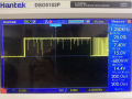
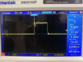
That doesn't look very tidy. Do you have enough decoupling across the UC3842?
Is the second one a gate waveform as well?
both of them are the gate voltage. I am using ucc2802. What do you mean by decoupling? Between UCC2802 (Controller) and MOSFET, I am using a Gate driver IC which is UCC27524.
 

Thread Starter

recker039

Joined Feb 27, 2025
16
What supply voltage are you using? What is the contactor coil's rated voltage?
Does the contactor have an auxiliary contact?
Do you have a problem if the contactor should open (for whatever reason) during the low holding current phase? There wouldn't be enough current to pull it back in.
My main supply voltage rate is between 110VAC and 220VAC (50Hz). It rectified through the Fullbridge Diode, which is used for driving the contactor. I use 110VAC coil.
No, I don't use any auxiliary contact.

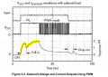
NO, the main problem is start-up current. Please see this application note of Using Motor Drivers to Drive Solenoids:
Access Denied

1740937687532.png
When I turn on power, the coil must draw high current for pull-in. My coil needs at least 7A. in low voltage rate as 110 to 170 VAC, it works! But at above 170 VAC, the MOSFET burns out. It burns immediately when the power is turned on.
 

Thread Starter

recker039

Joined Feb 27, 2025
16
Going back to the circuit shown in post #1, one possibility may be that the higher current with the higher supply voltage is increasing the voltage drop across that 1.3 ohm series resistor below the source terminal, which might effectively reduce the gate drive so that the mosfet is not switched into full saturation. That would greatly increase the heating immediately. The other possibility is a reverse breakdown of D7. That also would immediately cause a serious overload. Can you add a second diode in series with D7??
The other possible issue, with the voltage drop on R3, can be checked by adding a second resistor across R3, or shorting it out completely. What is it there for? Is it part of the gate drive circuit??
OK...Let's try!:)Now, I change my shunt in 0.54 ohm. According to your guess, the situation should improve from before. I will report the reason. But the current is approximately constant(between 6.5A to 7A). As a result, it should not work at low voltages.
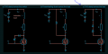
If D7 breakdowns, is it burn? I found a new idea but I haven't implemented it yet. There is:
1740938716201.pngFinally, you know... this improve transition position of ON to OFF MOSFET state.
 
Top