 Facebook
 Google
 GitHub
 Linkedin
I’m working on an RF application for a weighbridge system. The device’s role is to collect data from load cell sensors and transmit it to a receiver.
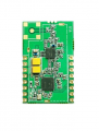
Old RF Board- CC1120+CC1190
The challenge:
What I did:
My Question:
Did I implement the connections correctly based on this schematic? If not, what changes should I consider to make the new RF module compatible with my existing firmware?


Old RF Board- CC1120+CC1190
The challenge:
- Our old RF module is no longer available, so I procured a new module that also uses CC1120 + CC1190.
- The difference is that the new RF module is designed for low-power applications, while the old one was not.
- In the new design, signals like TCXO, HGM, and VCCPA are controlled through GPIO. But our old firmware does not handle these GPIO controls.
What I did:
- Based on the attached schematic, I connected things as per my understanding.
- I designed a jumper board to fit new rf board into my old main board
- Initially, it worked for some time, but then stopped functioning. I tested multiple boards (both RF and MCU), but the issue persists.
- In the current board, the reset pin is kept high via a 4.7kΩ resistor, and I added a 6µF MLCC capacitor to provide an initial delay for oscillator stabilization.
My Question:
Did I implement the connections correctly based on this schematic? If not, what changes should I consider to make the new RF module compatible with my existing firmware?
Attachments
-
 473.5 KB Views: 1
 -
 138.6 KB Views: 1


