I am designing 24V_5A SMPS circuit by keeping reference of a mobile charger circuit...when I power on the circuit the IRF840(power Mosfet) blasted . What is the reason...Is there any mistake in the circuit diagram..?
in the absence of regulation, a flyback circuit transfers the same amount of energy each cycle, increasing the energy stored in the capacitor, and increasing its voltage until something fails.
in the absence of regulation, a flyback circuit transfers the same amount of energy each cycle, increasing the energy stored in the capacitor, and increasing its voltage until something fails.
This design relies heavily on the -ve feedback from the Aux secondary winding and the combination of the BA159/47u/2k2, whereas you just have an 1N4148 shorting out the feedback winding. Your feedback winding polarity relative to the output winding polarity is reversed - I suspect you aren't getting the feedback turn-off pulse this circuit requires. Did you wind the transformer yourself or are you using an off-the-shelf one?
No they aren't - the optocoupler plays a key role in capping the voltage generated at the secondary whereas your approach will see significant open-circuit voltages developing at the secondary especially on low loads.
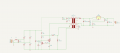
Looking at the reference circuit, there's a 3 turn winding which feeds back to the gate of the MOSFET to switch it off. Notice the dot on the winding, denoting the correct phasing (important on all windings).
Without that secondary I can't see how the circuit would oscillate correctly.
On low load the voltage at the input of the LM338 will keep increasing until the LM338 (or the capacitor) fails.
Another point is that the LM338 is a linear regulator - any excess voltage will be dissipated as heat, making it rather pointless to use a switched-mode circuit in the first place.
Let’s talk about the elephant in the room: the design of the flyback transformer.
You have not discussed, at all, the transformer details. A line-powered flyback transformer design is FAR from being trivial. More so if you choose a self-oscillating topology.
 Facebook
 Google
 GitHub
 Linkedin