MOSFET Battery swap issue

Thread Starter

eb_12345

Joined Jan 26, 2024
22
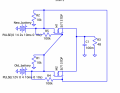
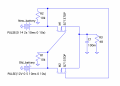
I am working on a battery hot swap system that will allow continuous power supply to a drone. I've created a system using P-MOSFETs, but I am running into some issues: There was an unexpected voltage drop when voltage was applied to one MOSFET at a time. This shouldn't have been the case since the gates should be grounded resulting in no voltage drop from the MOSFET. After about 30 seconds of applying voltage to the drain, the MOSFET gate properly grounded. I further found that when measuring the MOSFETs with the diode function on the multimeter M2 was reading .5V in both directions, while it should only measure in one direction because of the substrate diode, and M1 read 0V in both directions. I think this may be an issue with the MOSFET itself, or the way I am grounding the gate using the 10k resistor. Please let me know if you have any thoughts or advice.
 

Attachments

Thread Starter

eb_12345

Joined Jan 26, 2024
22
Im using Si7141DP P Channel MOSFETs, could that be the issue? When I try to do a continuity check between the drain and the source in order to check the body diode, I don't always get a beep which is a bit worrying.
 

Attachments

Thread Starter

eb_12345

Joined Jan 26, 2024
22
I realize I had the gate floating which doesn't do much good. Instead I used the diode tester on the DMM. When I used the diode function on the DMM, I placed the red probe (positive) on the source (higher voltage side) and the black probe (negative) on the drain (lower voltage side). This resulted in a voltage drop of approximately 0.5V from the body diode, which was expected. However, I only observed the expected voltage drop from one of the MOSFETs. When I flipped the leads, the reading showed 0L, but for the second MOSFET, it showed an open circuit instead. To ensure stability, I grounded the gates to maintain consistent behavior and the PCB was disconnected from the power supply. I guess this just shows that the MOSFET is faulty? But this may be concerning because I'm fairly certain the MOSFET was working properly when I soldered it in place.
 

Alec_t

Joined Sep 17, 2013
15,101
MOSFETs are static-sensitive, so touching a floating gate may have damaged the MOSFET. The gate should have been connected to the source through a low impedance, e.g a short, when using the DMM for the body diode check.
 

Thread Starter

eb_12345

Joined Jan 26, 2024
22
MOSFETs are static-sensitive, so touching a floating gate may have damaged the MOSFET. The gate should have been connected to the source through a low impedance, e.g a short, when using the DMM for the body diode check.
Would it be better to have the gate connected to the drain via a resistor (say 100k) in order to ensure the gate isn't floating when nothing is connected to it.

Something like the below:
 

Attachments

Alec_t

Joined Sep 17, 2013
15,101
Would it be better to have the gate connected to the drain via a resistor (say 100k) in order to ensure the gate isn't floating when nothing is connected to it.
Not if you're testing the body diode function. Connect source to gate to keep the FET off.
Btw, you have the P-FETs back-to-front in the switching circuit shown. Source should connect to battery positive.
 

crutschow

Joined Mar 14, 2008
38,316
you have the P-FETs back-to-front in the switching circuit shown. Source should connect to battery positive.
No.
That would block current to the load when both are connected.
The purpose of the P-FETs is to keep current from the higher voltage battery flowing into the lower voltage battery when the swap is being made.
So when both batteries are connected the substrate diodes block that current.

Below is the LTspice sim of the circuit:
When both batteries are connected the substrate diode is carrying the current from the higher voltage battery (note that Vout is one diode-drop below the Bat1 voltage when both are high).

1744292147668.png
 
Last edited:

Thread Starter

eb_12345

Joined Jan 26, 2024
22
So any suggestions to help with the buggy MOSFETs? I think the design is solid but not sure if the issue is just my handling of the MOSFETs and needing to be more careful with static discharge frying the gate. I'm currently using SI7141DP P-Channel MOSFETs
 

crutschow

Joined Mar 14, 2008
38,316
So any suggestions to help with the buggy MOSFETs? I think the design is solid but not sure if the issue is just my handling of the MOSFETs and needing to be more careful with static discharge frying the gate. I'm currently using SI7141DP P-Channel MOSFETs
Test the MOSFETs with a 1kΩ resistor in series with the MOSFETs drain to -5V and the source to common/ground.
Monitor the drain voltage will alternately connecting the gate to -5V and common.
The drain voltage should be -5V when the gate is grounded, and 0V when the gate is at -5V.

Replace any MOSFETs that don't work, and be careful about static discharge to their gates.
 

Thread Starter

eb_12345

Joined Jan 26, 2024
22
Makes sense. I think I'll do something similar but with a positive voltage. For example in this circuit when Vg + Vgth < 10V (Vs) ie. Vgs < 0, the MOSFET will turn off resulting in 0V at the current. I'll then flip the drain and source and the result should be that there is voltage drop as a result of the MOSFET being off when Vg + Vgth < 10V (Vd), ie. Vgs < 0. In this the drain is acting as the source like in the full circuit. It's interesting how the source and drain can be switched in relation to the gate voltage. I supposed it just depends which is at a higher voltage. In the case of the battery swap, the drain is at a higher voltage so the conduction is dependent on Vgd, as opposed to Vgs
 

Attachments

crutschow

Joined Mar 14, 2008
38,316
Yes, MOSFETs conduct equally well in both directions when biased ON.
But it only blocks in one direction when OFF, due to its substrate diode from drain to source.
 
Top