Use a mosfet to disconnect a load while charging an 18650 Li-ion battery

Thread Starter

FrankTep

Joined Dec 25, 2025
9
Hi all,

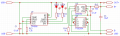
I want to use a AO3401A p-channel mosfet to disconnect a load while charging an 18650 Li-ion battery via a TP4056 (with protection) module. The load needs 3.8–4 V and up to 2.5 A at peak. When a 5 V adapter is plugged in, the load should turn off and turn on once unplugged. Added a 1K resistor between IN+ and G, and an ESD TVS diode SMAJ5.0A on the gate pin to protect against ESD, not sure how correct it is though.
Are the components and wiring below correct for my purpose?
Capture.PNG
 

KeithWalker

Joined Jul 10, 2017
3,603
The best way to find out is to bread-board it and see what happens. Then, if there are any problems, you can try different solutions for the best results.
 

Thread Starter

FrankTep

Joined Dec 25, 2025
9
@crutschow
See my TP4056 (with protection) below.
It takes 5V as input (to recharge the battery) and has Out+/- for the load.
Capture.PNG
@KeithWalker
This is possible but since it'll be used in a box as the final product working for a long term, I need to make sure the components and wiring are correct.
 

crutschow

Joined Mar 14, 2008
38,316
Okay, your circuit should work but the TVS diode needs to be connected between the MOSFET gate and ground, and the 10k resistor connected to ground.
 

sparky 1

Joined Nov 3, 2018
1,218
The TP4056 is designed to regulate charging for a single cell Li-ion such as the 18650 battery.
These newer batteries need specific handling. Switching can be useful but uses a parallel module, enable pin high/low
The datasheet has given module builders a guideline and there are some hacks that (work sort of) but there are many that will not meet requirements.
A closer examination of the charging circuit design that is specified and the compromise that a modified circuits quality effects battery life, the goal of TP4056.

The block diagram on page 8 along with the graphs is specific. 18650 very useful battery and the TP4056 is interesting as a matching circuit.
The modules lettering does give rise to purpose being either / or but not both charge controller, a loose battery charger.
1809261820_TOPPOWER-Nanjing-Extension-Microelectronics-TP4056-42-ESOP8_C16581.pdf

Possibly you might expand on the LOAD and some ideas might find solution. For example a clock circuits can have power out battery backup.
A Schottky diode like BAT54 or array could detect when the power is out and a small load could draw for example 20 mA from the battery for some time.
If you include a safe limit into the design, the fire risk could be low and it would not combine both charging and powering using a single TP4056 at the same time.
 
Last edited:

MrAl

Joined Jun 17, 2014
13,667
@crutschow
See my TP4056 (with protection) below.
It takes 5V as input (to recharge the battery) and has Out+/- for the load.
View attachment 361130
@KeithWalker
This is possible but since it'll be used in a box as the final product working for a long term, I need to make sure the components and wiring are correct.
Hello,

That's a dev board not a raw IC chip. That means it already has some other components on it that may be of use.

Is the attached drawing a schematic of your dev board?

It seems like a stupid design because it looks like there is no power management, and both charging and loading at the same time is said to possibly damage the cell.
To me, that makes it questionable to even use this board at all, except for purely charging a cell with no load, maybe.
The questions is, why didn't they include the extra MOSFET in the first place.
 

Attachments

Last edited:

sghioto

Joined Dec 31, 2017
8,633
The TO4056 module:
When 5 volts is connected the battery is charging and disconnected from the load while sending a regulated 4.2 volts to the output pins.
The TP4056 is rated 1200ma max including charge current and load.
R13 sets the maximum charge current which is 1amp at 1.2K

1766808014250.png
1766811163889.png
 
Last edited:

Thread Starter

FrankTep

Joined Dec 25, 2025
9
@sparky 1
- I use the module to recharge two 18650 li-ion batteries packed in parallel. I doubt if there'll be any issue with this. It's pretty much like one cell with a high capacity. Charging may take more time though.
- not sure I got the rest of talks correctly, sorry.

@MrAl
- my circuit will be used in a final product. What power management do you mean? And this is indeed not to both charge the cell and give power to the load at the same.

@sghioto
- currently the load gets power from the battery whether or not 5V USB is inserted. My circuit is to disconnect the load if 5V is inserted.
- thanks for the wiring. Seeming it's what @crutschow meant.
- is that schematic correct to use for "TP4056 with protection"? If so, likely I can combine this with my circuit then use it on a PCB.

@crutschow
You meant this:
Capture.PNG
-don't you suggest using a SMBJ6.0A rather than SMAJ5.0A?
 

MrAl

Joined Jun 17, 2014
13,667
@sparky 1
- I use the module to recharge two 18650 li-ion batteries packed in parallel. I doubt if there'll be any issue with this. It's pretty much like one cell with a high capacity. Charging may take more time though.
- not sure I got the rest of talks correctly, sorry.

@MrAl
- my circuit will be used in a final product. What power management do you mean? And this is indeed not to both charge the cell and give power to the load at the same.

@sghioto
- currently the load gets power from the battery whether or not 5V USB is inserted. My circuit is to disconnect the load if 5V is inserted.
- thanks for the wiring. Seeming it's what @crutschow meant.
- is that schematic correct to use for "TP4056 with protection"? If so, likely I can combine this with my circuit then use it on a PCB.

@crutschow
You meant this:
View attachment 361171
-don't you suggest using a SMBJ6.0A rather than SMAJ5.0A?
Hi,

I meant the power management to manage the circuit when a load is applied, or not applied, such as with that extra MOSFET.
Why would they not include that in the original design. If someone uses this to charge and run the load at the same time the battery could become overcharged, and we know that is not good.

Maybe they assume the load would not be connected for very long or something.
 

Thread Starter

FrankTep

Joined Dec 25, 2025
9
@MrAl
- yes, it'd make more sense if they designed the module that way, that's why I asked @sghioto to make sure if the schematic is correct to later on use it with my circuit for a more complete module (disconnect the load when recharging the battery)
 

sghioto

Joined Dec 31, 2017
8,633
that's why I asked @sghioto to make sure if the schematic is correct to later on use it with my circuit for a more complete module (disconnect the load when recharging the battery)
Would it be better if the 5 volt supply was able to charge the battery and supply power to the load?
The battery would be disconnected from the load while charging as before.
 

Thread Starter

FrankTep

Joined Dec 25, 2025
9
@sghioto
The load needs 3.8-4.2V and 2.5A at peak to work and 5V will damage it. Also, typical smartphone 5V adaptors, which will be handy to recharge the device's battery, usually provide 1A.
 

sghioto

Joined Dec 31, 2017
8,633
@sghioto
The load needs 3.8-4.2V and 2.5A at peak to work and 5V will damage it. Also, typical smartphone 5V adaptors, which will be handy to recharge the device's battery, usually provide 1A.
Correct, would need a 3 amp minimum 5 volt supply.
Sample circuit, D2 along with the loss across M2 drops the output voltage to appx 4 volts.
1766859100367.png
 

Thread Starter

FrankTep

Joined Dec 25, 2025
9
@sghioto
- so by a 5V 3A adaptor and your circuit above it will be possible to:
1) disconnect the load from the battery when charging it
2) charge the battery faster (since it's now 3A not 1A)
3) feed the load using the adaptor when it's plugged
4) feed the load using the battery when the adaptor is unplugged
right?
 

sghioto

Joined Dec 31, 2017
8,633
@sghioto
- so by a 5V 3A adaptor and your circuit above it will be possible to:
1) disconnect the load from the battery when charging it
2) charge the battery faster (since it's now 3A not 1A)
3) feed the load using the adaptor when it's plugged
4) feed the load using the battery when the adaptor is unplugged
right?
1) Correct, same thing as saying it disconnects the battery from the load when charging.
2) No, the TP4056 limits charging current to 1amp max.
3) Correct.
4) Correct.
 

Thread Starter

FrankTep

Joined Dec 25, 2025
9
@sghioto
>>No, the TP4056 limits charging current to 1amp max.
- why should it limit the current to 1A only? Any issue with charging the battery with 3A?
 
Top