Facebook
 Google
 GitHub
 Linkedin
I've attached two files.
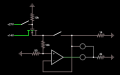
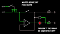
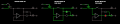
The one with the three diagrams shows the simulation working as intended. The one with only one diagram shows a result I don't understand.
I'd like this circuit to do three things:
- Only turn on when a master device is turned on as well and turn off when the master is turned off. I'm doing this with a MOSFET
- Protect for overcurrent (5A). I'm doing this with a fuse (represented by a switch in this simulation)
- Have a status LED. off when off, green when on and the fuse isn't blown, red when on and the fuse is blown
If i used a normally open relay to turn on and off according to the voltage given by the master device I know this would work, but I'd like to do it with a MOSFET to keep the build small as I have several of these to fit in the enclosure.
Is there something I don't understand about MOSFETs used as switches? Could this be a glitch of the simulation?
If so, what characteristic / parameter do I have to look for to select the proper FET for this application once I'm ready to go to the breadboard?
Attachments
-
 83.3 KB Views: 6
 -
 124.8 KB Views: 5