About Battery Bypass Circuit Design

Thread Starter

Kodai

Joined Jan 3, 2025
7
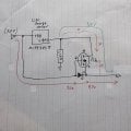
I'm a beginner and am designing a battery-powered device.
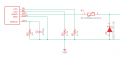
- When the power supply is connected, charge the battery while supplying power to the load (red line in the photo).
- When the power supply is disconnected, supply power from the battery to the load (blue line in the photo).
I'd like to achieve this function, and I'm considering the circuit shown in the photo using the Gemini 3 Pro, but I have a few questions.

1. Why is a Schottky diode inserted?
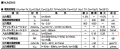
The MOSFET datasheet says it turns on between -0.5V and -1.2V. In this case, it turns off even when the voltage difference is 0V without the SBD, or +0.3V through the SBD. I don't understand why there needs to be a voltage difference between the gate and source.
Is it something to prevent backflow to the power supply, like back electromotive force?

2. Regarding reversing the MOSFET's drain and source.
As I've learned more, it seems like this circuit works with either the drain or source.
Can you refute this, or explain why and suggest which connection is recommended?


(Also, is the Gemini 3 Pro weak at electronic circuits? The hardware answers seem less stable than the software answers.)

translated
Thank you, I'm waiting for your reply
 

Attachments

MisterBill2

Joined Jan 23, 2018
27,159
I am not familiar with using the Gemini 3 Pro, so I am not able to comment on it's capabilities.

What reference designs have you looked at? I have found that examining previous designs can be very useful. and also educational, if they include explanations of how they are intended to function.
 

Tonyr1084

Joined Sep 24, 2015
9,744
This is what you're asking for.
View attachment 359629
There's no need for the FET. As for how well it will work - "What is your battery voltage?" If it's a 5V battery then it's likely two cells, meaning it's a 7.6V battery system. Unless your charger is also a buck/boost converter you'll never charge the battery to anything useful. If your battery is a single cell then it's 3.8 volts. If the 5V source goes down your circuit - whatever you're powering - probably won't work, not on 3.8V.

As for your question about why a Schottky diode - it has a low forward voltage. The P-FET will have a lower voltage drop but it will still be less voltage than you want. The only reason I can see for the Schottky is to limit the lost voltage.

So, what voltage is the battery?
 
Last edited:

MisterBill2

Joined Jan 23, 2018
27,159
Like Tony mentions,, the battery is probably not 5.0 volts. From the sketch in post #1, I am guessing single cell, 3.8 volts. What is the proposed charger voltage?? I see options not needing diodes as being possible.
 

MisterBill2

Joined Jan 23, 2018
27,159
Properly designed DC power supplies are not subject to damage from a voltage connected to their output terminals That certainly includes supplies used for battery charging.!!I have seen quite a few instances of DC applied directly to a battery pack that is powering some device or appliance. Often a portable radio.
 

Thread Starter

Kodai

Joined Jan 3, 2025
7
Sorry for the late reply. Thank you, everyone.
I'm still new to this, so I didn't know the standard way.
The battery is 3.8V per cell. So it just uses the rule that voltage flows from high to low.
I will study more.
Thanks a lot!!
 

sghioto

Joined Dec 31, 2017
8,633
The battery is 3.8V per cell. So it just uses the rule that voltage flows from high to low.
To be clear there's appx a 0.3 volt loss through the diodes depending on the current.
Meaning the output voltage on battery is 3.5V and 4.7 on 5V supply.
Is that acceptable?
 

Tonyr1084

Joined Sep 24, 2015
9,744
Late entry (forgot to post hours ago) OK, so we eliminate the upper diode. The lower diode is critical thought. Uncontrolled voltage feeding a Li-Po battery will cause much excitement, smoke and flame.

Bottom line, the TS circuit is a non-starter. It should not be tried the way he has it sown. Plus, the voltages are all wrong. You need more than 5 volts to charge a 5 volt battery. The RIGHT way would be to start with a 12 volt supply and buck it down to the needed voltage - the TS case - 5 volts. Meanwhile the battery charger would be charging the battery to a higher voltage than needed then that voltage gets bucked down to the necessary 5 volts.
 

Tonyr1084

Joined Sep 24, 2015
9,744
The battery is 3.8V per cell.
Per cell ? ? ? How many cells? How are they wired? Parallel? Series?
You really need a complete redesign for your circuit. To get there you need to share with us the starting voltage, whether it is DC or AC and what the final use/purpose is. What are we powering? How long does it need to run if on battery power?
 

Thread Starter

Kodai

Joined Jan 3, 2025
7
To be clear there's appx a 0.3 volt loss through the diodes depending on the current.
Meaning the output voltage on battery is 3.5V and 4.7 on 5V supply.
Is that acceptable?
I forgot to think about that.
The dropout voltage of the output buck regulator NJM2845DL1-33 is 0.28V at worst.
The required voltage of the ESP32-WROOM-32E load is 3.3V.
In this case, there's no problem when using external power, but when running on battery power, I think the system needs to shut down at a battery output of 3.58V.
I'm planning to monitor the voltage using the R3111 series.
Also, regarding the reduction in operating time when shutting down early, as shown in the attached graph, the remaining capacity at 20°C drops sharply at 3.6V, so I don't think it will have much of an impact.

Is this correct?
Thank you for pointing that out.
 

Attachments

Thread Starter

Kodai

Joined Jan 3, 2025
7
Per cell ? ? ? How many cells? How are they wired? Parallel? Series?
You really need a complete redesign for your circuit. To get there you need to share with us the starting voltage, whether it is DC or AC and what the final use/purpose is. What are we powering? How long does it need to run if on battery power?
Connect only one LiPo cell

DC5V

MCP73831
Lipo charge controller

Lipo 1cell 1000mAh

NJM2845DL1-33
Buck Regulator
Dropout Voltage 0.28V, Output Voltage 3.3V

ESP32-WROOM-32E
Microcontroller
Input voltage: 3.3V
Current consumption: Approx. 500mA
 

MisterBill2

Joined Jan 23, 2018
27,159
One more thought: or a couple of thoughts: What about that "5 volt" source?? Is it an actual regulated power supply?? Or a "5 volts" wall-wart charger? Or possibly an older non-regulated wall wart, that only provides the rated voltage at the rated current??
If it is only charging the battery while the load is active, the battery will provide some amount of stabilizing influence.
I am not at all familiar with the "ESP32" modules and so I am not aware of the accuracy requirements of their power supply, or the supply noise limitations.
 

Thread Starter

Kodai

Joined Jan 3, 2025
7
As shown in the image, my design uses a USB-C charger as the 5V power source. I'm assuming the charger complies with the USB standard, so I'm not too concerned about the voltage.

Regarding the "stabilizing influence," you mean that if the power supply input voltage momentarily drops (specifically, [Power Input V] < [Battery Output V] -[Diode Drop V]), the battery will supplement it to keep the voltage up. Is that correct?

Thank you.
 

Attachments

MisterBill2

Joined Jan 23, 2018
27,159
In many designs, the battery internal resistance is less than the rest of the circuit,, so that it tends to limit the voltage changes as the load current varies. The amount of the stabilizing influence may be limited by the external circuitry, though.
 
Top