 Facebook
 Google
 GitHub
 Linkedin
Hello,
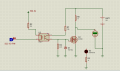
Pictures attached.
Is this circuit reliable to convert 5V into 24V? Let me know if you think I should consider other factors. I'm not very experienced when it comes to design.


Pictures attached.
Is this circuit reliable to convert 5V into 24V? Let me know if you think I should consider other factors. I'm not very experienced when it comes to design.
")


