No. Technically a class C amp is an amp that conducts less than 180 degrees. If a switch is on for 30% of the time and off 70% of the time........it has the same conduction ratio.....but a different function.
If a switch is on half the time and off the other haft.......that would be class B. But we don't call switches,....amplifiers,.....we call them switches.
An amplifier tries to replicate a portion of the input signal faithfully to the output.
But a switch is usually only concerned with switching speed.
The ratio of on time to off time controls the power delivered....without any concern for distortion.
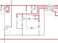
I figure l am asking the wrong question. Basically, how does it work? It is part of a Yamaha amplifier. The DC-DC converter section. It is being fed by the SMPS. I have the amp, and what got me interested was the transistor base is at -.4 volts. That how I got the idea of Class C.
If you have time BR-549, I have a few questions about this circuit. I do have a basic understanding, I worked in car audio most of my career, just not familiar with SMPS theory.
What is the zener for, and what is the discharge path of the RC circuit?
I have some time. Let's see if you can figure out why and how it works.
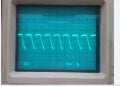
Get your DMM and scope.
Please check on circuit board for the presents of C3750 and R3751.
Do you have a link for the full print?
BR-549, I will get you the link for the manual, I have a working amplifier and can get you all the readings you need. I am currently out of town and can't access the files now. What I have on my IPad is that photo. I can tell you there is +9 volts at the zener and capacitor 3751 junction. C3752 is -4.6 volts. The supply is +5.6 volts.
Thanks Albert, this circuit is fascinating, for example, what determines the duty cycle? Why is the transistor base at -.4VDC? If C3751 does discharge, where is the path? Fun stuff.
Class-C is often used on the PA stage of transmitters - typically the drive waveform saturates the transistor only at the peaks, a large pulse of collector current excites the tuned circuit and flywheel action does the rest.
Class-D is a comparatively recent audio trend - it uses PWM with no linear operation to obtain similar efficiency to a typical SMPSU.
This is great information. There is so much to this little circuit. I am trying to determine both AC and DC circuit behavior. I may be in over my head at this point. Not the troubleshooting aspect, just the engineering side. If you have any more pointers, feel free to add them.
Put your scope on the base........and see how long the base is at a - .4 VDC.
" I can tell you there is +9 volts at the zener and capacitor 3751 junction."
I can't find a zener - C3751 junction.
Without knowing basic electronics.........our explanations will be confusing. You can not learn this stuff from the top down.
With your knowledge......the best that can be done is to show you what different parts of the circuit are doing at the same time.
BR-549, sorry, no zener at C3751. I know basic electronics. The base is -.4VDC referenced to ground. C3752 is charged to -4.6 volts referenced to ground. I have a dual channel scope. Showing how each part of the circuit works would be a tremendous help.
 Facebook
 Google
 GitHub
 Linkedin