Is my simulation correct in LTspice?

Thread Starter

alekwyp

Joined Mar 19, 2025
14
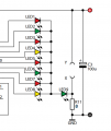
I have to simulate this schematic in LTspice. The problem is, that it uses an CMOS 4017N counter. I've only found one libary which has that element, but it has different inputs. The main problem i have, is that i dont have the VDD input. On the first picture is my project, and on the second one is the schematic. If it is needed i can attach my project folder also in the comments.1742397490577.png1742397506214.png
 

crutschow

Joined Mar 14, 2008
38,316
The main problem i have, is that i dont have the VDD input.
The Vdd power and ground connections to the CD4000 devices are hidden in LTspice to minimize clutter in the schematic .
The .inc CD4000_V.lib command makes those connections from your external Vdd voltage and circuit common to the CD4000 devices.
You don't have to change the voltage in the symbol parameters from its default 5V.
 

Thread Starter

alekwyp

Joined Mar 19, 2025
14
Thanks for the response, guys. My circuit should sequentially light up the LEDs 1-8 in a loop, while LED 9 should stay on all the time. So, in this case, is the circuit working correctly? The circuit is powered by a 9V LED, which is why there is 9V on the CMOS 4017 counter. This is my first time working with such a complicated circuit in LTspice, so I wasn't exactly sure what I was doing.
 

ericgibbs

Joined Jan 29, 2010
21,390
Hi,
Although the VDD of the 4017 is set to 9V, the loading caused by directly driving an LED without a series current limiting resistor will pull the output down to approx 4V.
E
EG57_ 2755.gif
 

eetech00

Joined Jun 8, 2013
4,704
Hi

I've included a new symbol in zip.

When using the CD4000_v.lib library, the VDD=9 symbol attribute sets the internal timing delays
of the model and doesn't affect the operating voltage, but you want them both to match.
In addition, "VDD" must be present as wire label or errors will be produced.

The .param VDD=9 statement sets the circuit supply voltage as well as the timings for the CD4017B model.

1742409643568.png
 

Attachments

Bordodynov

Joined May 20, 2015
3,429
Wow, thank you all guys very much for help i really appreciate that :)
Your simulations are not correct! A voltage greater than the breakdown voltage develops at the Base-Emitter junctions! LTspice allows you to simulate a breakdown. I've brought out the voltages on all the bases:
Vbase.png
 
@alekwyp
Seems you didn’t place a C4 to your circuit.
It creates a change in speed of running the light according frequency of left multivibrator due to continuous charging/discharging the C4.
 
Last edited:
Top