Is my Schematic Ok?

Thread Starter

kowshik1729

Joined May 10, 2020
20
Hello guys,

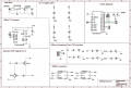
I have developed a design with Espressif products and I attached the schematic in the attachments.

Hence I need thoughts on following things

1. Is my Rx and Tx toggling LED's connections are correct?

2. As I made voltage coming from USB as the common power source, will it be able to drive the whole circuit on the board? (This is my major concern) Please let me know.

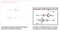
3. The Io0 and EN toggling circuit is correct? I made this in order to automatically upload the code into ESP32-Wroom instead of pressing EN and BOOT buttons.

Please give me suggestions and do correct me in case I made any wrongs. Suggestions are much much appreciated. Thanks in advance guys...!!

review_schematic.png
 

dl324

Joined Mar 30, 2015
16,943
Your schematic drawing method is atrocious to read. Constantly having to search for and refer to some "remote" connections is tedious.

What is the current sink capability of the microcontroller?
1589123538511.png
 

Thread Starter

kowshik1729

Joined May 10, 2020
20
Hi,

Thanks for replying. Oops...! Sorry for that. I actually posted a picture because it would be easy for you to directly access and look the image instead of sharing my .sch file.

Actually I didn't get what exactly did you ask for when you told What is the current sink capability of the microcontroller?
assuming you asked for current consumption, it's around ~200mA.
 

SamR

Joined Mar 19, 2019
5,052
Sink - When you have an externally powered device connected to a uController pin, how much input power (mA, V) is the pin rated for?

Source - When you have a uContoller powered device connected to a uController pin, how much output power (mA, V) can the pin provide?
 

Thread Starter

kowshik1729

Joined May 10, 2020
20
Sink - When you have an externally powered device connected to a uController pin, how much input power (mA, V) is the pin rated for?

Source - When you have a uContoller powered device connected to a uController pin, how much output power (mA, V) can the pin provide?
Thanks sam. So as I mentioned the MCU is powered through USB, the sink current is 200mA.:)
 

dl324

Joined Mar 30, 2015
16,943
I actually posted a picture because it would be easy for you to directly access and look the image instead of sharing my .sch file.
The connection lines disappear when I zoom out enough to get a bigger picture. Don't post your .sch files. You should print to PDF in black and white.

That still won't improve on your "disjointed, spaced out" drawing style. I've seen others use that style, but that doesn't mean it's worth emulating.
Actually I didn't get what exactly did you ask for when you told What is the current sink capability of the microcontroller?
assuming you asked for current consumption, it's around ~200mA.
What is the sink capacity of the I/O pins? You're trying to sink around 10mA.

If 200mA is the total consumption, a USB adapter should accommodate that. If you're taking power from a USB port/hub, you'll be in violation of the USB spec which only allows 1 USB load unless you negotiate for a higher power mode. A standard load is 100mA for USB2 and 150mA for USB3.
 

Audioguru again

Joined Oct 21, 2019
6,705
Your schematic had faint pink lines that could barely be seen and tiny text that could not be seen. I increased the contrast a lot and now most things can be seen but still everything is tiny.
Things are tiny because they are too far apart. Your schematic has a lot of wasted space. If the spacing is closer then everything will be larger and easier to be seen. I did not bother changing the spacing, you do it.
 

Attachments

Ylli

Joined Nov 13, 2015
1,088
Sheesh, just about every component with only node names on their leads. How can anybody read this and be able to understand the interconnectivity of the parts? A schematic should *show* all the parts connected as they are connected with minimal node only points. With the few components here, put it all on one page with the interconnects shown. E.G.
Annotation 2020-05-10 123411.png
 

SamR

Joined Mar 19, 2019
5,052
Thanks sam. So as I mentioned the MCU is powered through USB, the sink current is 200mA.
Not Total, Each Individual I/O pin. Typically different values for sink/source. Check the PDF for data on that uC. The total Source of all Output pins + uC operating Overhead = uC power needed. The total power into each input pin is the total Sink of the uC.
 
Last edited:

n1ist

Joined Mar 8, 2009
189
The on-chip 3v3 regulator on the CP2104 can only provide 100mA, including the current used by the 2104 so you would need an external regulator if you are pulling 200mA
/mike
 
Top