is my LPF schematic ok?

Thread Starter

abc77

Joined May 10, 2017
59
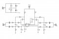
i made a LPF schematic using op-amp and wanted to ask whether this is ok.

At connector J4 where I want to connect 10V or 15V supply. Is the the ground connection in the circuit ok?
 

Attachments

Marley

Joined Apr 4, 2016
502
Should you make J3 3-pole so that you can have a 0V reference for your outputs?
I realise that J1 and J2 are balanced inputs but I would have an extra pin on these as well for a screen connection.

I assume you are using a single 15V supply with R6 and R7 dividing for the 0V rail - should be OK.
 

Thread Starter

abc77

Joined May 10, 2017
59
@atferrari,
i have not made the circuit because i think it is wrong. i did the simulation. when i connect +/- 15V directly to the opamp the output is ok. however when i apply the through the voltage divider circuit as shown the required output signal is not there.

i am having difficultly in understand where the ground signal of opamp, the input signals goes and the 30V(or 15V) supply goes!

@Marley,
the inputs are you said are differential signals, and the output is single ended signal. the two outputs are left and right audio signals to be connected to headphone. do i need the third pole? i connected the headphone ground to the ground of the LPF(opamp) circuit.
 

Attachments

Top