Is LTSpice consistenly analyzing identical circuits differently?

Thread Starter

maxi1010

Joined Jul 19, 2026
1
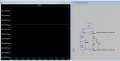
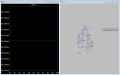
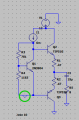
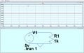
Ive experienced this issue a lot, where LTSpice gives me compeltely different results with identical circuits stored on different files. So ive included images of quiescent currents measured at the top 0.47 ohm resistor on an AB amplifier circuit. Is there any logical reason why LTSpice is giving me comepletely different currents?
 

Attachments

WBahn

Joined Mar 31, 2012
33,021
Ive experienced this issue a lot, where LTSpice gives me compeltely different results with identical circuits stored on different files. So ive included images of quiescent currents measured at the top 0.47 ohm resistor on an AB amplifier circuit. Is there any logical reason why LTSpice is giving me comepletely different currents?
Giving a single data point isn't very helpful.

Please post your .asc files so that we can examine them, or at least post the complete operating point values for each circuit.

Putting a ground symbol on a wire that crosses it at 90° should make a connection, but notice that there's no connection dot, so it's hard to tell.

Look at the SPICE netlist and see whether the two netlists are the same.
 

crutschow

Joined Mar 14, 2008
38,607
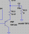
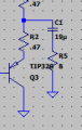
It would appear the PNP transistor is incorrectly labeled in the left picture below:
It looks you've put TIP32G as the reference designator (which should be Q3).
The PNP designation should be replaced by TIP32G.

So it seems it's not an LTspice problem, it's cockpit error. :rolleyes:


1784481925785.png 1784481974063.png
 
Last edited:

Papabravo

Joined Feb 24, 2006
22,096
Ive experienced this issue a lot, where LTSpice gives me compeltely different results with identical circuits stored on different files. So ive included images of quiescent currents measured at the top 0.47 ohm resistor on an AB amplifier circuit. Is there any logical reason why LTSpice is giving me comepletely different currents?
Keep in mind that you can run the same file with many different combinations of program parameters. In particular you have different integration methods and handling of initial conditions. There are also numerical tolerances and other adjustments that allow for faster or more reliable convergence. I would become very familiar with all the settings to ensure consistent and repeatable results across platforms or files that may have directives in them you are not aware of.
 

BobTPH

Joined Jun 5, 2013
11,593
That ground symbol is NOT connected to that wire. The connection to the ground is above the triangle, as you can see when you make a new ground.
 

ci139

Joined Jul 11, 2016
2,013
without looking at your pictures . . .

there might be a difference when you split R (or C or L) into N×(R/N) or use a different <Maximum Timestep> . . . maybe more (such as use a different build / update-level of LTspice)
 

panic mode

Joined Oct 10, 2011
5,134
That ground symbol is NOT connected to that wire. The connection to the ground is above the triangle, as you can see when you make a new ground.
i've been using LTSpice for a while and have it on machine in front of me.
1784566803113.png

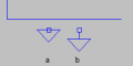
a. this is how GND symbol actually looks like in LTSpice . connection point is on the triangle...
b. this is how GND symbol should look like (photoshopped).
 

WBahn

Joined Mar 31, 2012
33,021
That ground symbol is NOT connected to that wire. The connection to the ground is above the triangle, as you can see when you make a new ground.
The ground symbols IS connected to that wire. Do a simple test and verify it for yourself (though it would sure be nice if the TS would post their .asc files or at least the netlists for the two circuits).

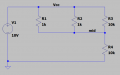
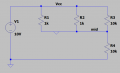
Consider the following LTspice schematic:

1784570374419.png

Here's the netlist:

Code:
* C:\AAC\Draft6.asc
R1 Vcc mid 1k
R2 Vcc mid 1k
R3 Vcc mid 10k
V1 Vcc 0 10V
R4 mid 0 10k
.backanno
.end
You can clearly see the connections to the node named 'mid'.

Here's the schematic after adding the ground connection directly onto the wire between R1 and R2.

1784570503690.png

Here is the resulting netlist:

Code:
* C:\AAC\Draft6.asc
R1 Vcc 0 1k
R2 Vcc 0 1k
R3 Vcc 0 10k
V1 Vcc 0 10V
R4 0 0 10k
.backanno
.end
Here you can clearly see that node 'mid' now netlists as node '0'.
 

WBahn

Joined Mar 31, 2012
33,021
Yes. But poor drafting practice.
Thus, it’s poor communication.
I doubt few people would argue with that -- the fact that people are clearly interpreting it in different ways underscores that point. But, that doesn't change that that's how the schematic is drawn and providing concrete evidence for what it actually means as opposed to what some people want to assume that it means is in no way endorsing doing it that way.
 

WBahn

Joined Mar 31, 2012
33,021
The LTSPICE I use has only b, I have never seen a.
I've only seen (a):

1784663291705.png

I'm not running the latest version (running 17.0.35.0), but I would imagine that the latest versions must still support this symbol in order to be backwards compatible with all of the schematic files made over the years.

Not, the icon on the toolbar has the tail, but that's just a picture on a toolbar.

1784663439669.png
 

Papabravo

Joined Feb 24, 2006
22,096
I've only seen (a):

View attachment 369766

I'm not running the latest version (running 17.0.35.0), but I would imagine that the latest versions must still support this symbol in order to be backwards compatible with all of the schematic files made over the years.

Not, the icon on the toolbar has the tail, but that's just a picture on a toolbar.

View attachment 369767
(a) is the only one I've ever seen in LTspice III (aka Switcher Cad), LTspice IV, LTspice XVII, LTspice 24 and LTspice 26. It has been that consistent on the Windows version since 1999, a period of 27 years. No connection shows on the symbol regardless of the direction of the connecting wire: horizontal or vertical.
 
Top