That will cause a very non-linear motor speed versus pot position.Either put the motor in the drain path of the NFET or use a PFET instead.

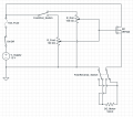
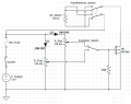
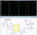
Putting the motor in the drain makes the motor vastly less controllable. In the source the voltage would at least be fairly consistent versus the pot setting, though the maximum motor voltage would be around 8 volts. The IRF540 has a minimum transconductance of 8.7 S (spec'd at high current, but that's all we have for a numeric value). The motor requires 0.12 A maximum. This means a delta Vgs of only about 14 mV above the gate-source threshold voltage will change the motor current from zero to maximum. For a typical single-turn pot this would be about 0.3 degrees of rotation with 12 volts on the pot.The motor was moved to the Drain and two VR100K will be as in parallel, so moved it to the Gate(or you can in series two diodes for each VR100K), the 1M resistor is added to avoid during the switch is switching from R-Dial to R_Foot still keep a low level and not open state, you can ignore the 1M resistor and then it will be as your circuit when you put the switch on the left side.
View attachment 158739
Using the MOSFET and adjust its Vgs to control the speed, the control voltage range will be too narrow, for a MOSFET that it is use as the ne555 pwm motor controller more easy to control the speed, but I didn't suggest it, because I just follow what the TS did.Putting the motor in the drain makes the motor vastly less controllable. In the source the voltage would at least be fairly consistent versus the pot setting, though the maximum motor voltage would be around 8 volts. The IRF540 has a minimum transconductance of 8.7 S (spec'd at high current, but that's all we have for a numeric value). The motor requires 0.12 A maximum. This means a delta Vgs of only about 14 mV above the gate-source threshold voltage will change the motor current from zero to maximum. For a typical single-turn pot this would be about 0.3 degrees of rotation with 12 volts on the pot.
Please recheck the two VR100K from the Vg. of MOSFET.The diodes in the pot circuits contribute nothing.
You still didn't get why I did it, they were used to avoid the two VR100K in parallel and affecting each other, because the pin2 of two VR100K are connected together and another pin probably pin3 are connected to ground.but the diodes in your version do nothing

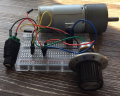
Referring to the reason for the comment 'the first 90 degrees or so of the pot did nothing. '!I had about 9V (max) and yea the first 90 degrees or so of the pot did nothing.
The motor seems to start fine, even at low voltage.
That significantly changes the design as compared to your circuit schematic, which only shows 120mAthe circuit will also see up to 10amps
Not for that current level.I thought making an analog circuit would certainly be cheaper in the long run than running a digital PWM circuit

I agree. The OP's circuit has a number of problems. PWM would be much better.That will cause a very non-linear motor speed versus pot position.
| Thread starter | Similar threads | Forum | Replies | Date |
|---|---|---|---|---|
|
|
Schottky diode with low leakage current | General Electronics Chat | 8 | |
| U | Generator fuel shutoff circuit diode selection. | General Electronics Chat | 20 | |
|
|
10A10 diode - Schottky? | General Electronics Chat | 34 | |
|
|
TVS diode working principle | Homework Help | 11 | |
| T | Capacitor-diode voltage multiplier | General Electronics Chat | 16 |