IRF520 is a enhancement-mode MOSFET. So to turn-on the transistor the gate-to-source voltage must be greater than the threshold voltage (Vg(th) in datasheet).
The IRF520 is an old (obsolete) NFET which requires a Gate-to-Source voltage of almost 10V to turn it on. A lot of newbies find this out when they try to use it as a switch controlled from an Arduino pin. More modern NFETs (sold as logic gate FETs) turn on hard with 5V or less on their Gate.
IRF520 is a enhancement-mode MOSFET. So to turn-on the transistor the gate-to-source voltage must be greater than the threshold voltage (Vg(th) in datasheet).
That's not sufficient if you want a switch as the op asked.
.
It's a common error to think that applying Vgs(th) will turn on a MOSFET as a switch. Vgs(th) is defined as the voltage where the transistor just starts conducting (current in the low or fractional mA region). To fully turn on the IRF520 as a low-resistance switch you need a Vgs of 10V as Mike noted, and which is stated in the data sheet where the test conditions for measuring the ON resistance value are specified.
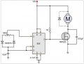
Back to the original, posted circuit: With the Gate driven from the 555 output pin, with the 555 powered from 12Vdc, the IRF520 will turn on properly. However, its On resistance is horrible (>0.25Ω). There are much better NFETs available for this application.
Also, a mystery to me is why the 1K pull-up resistor from Gate to +12V is there? It is not needed, it just wastes power, and could create a runaway motor...
It's a variable speed motor drive. Turn the pot to make the motor speed up or slow down.
You should check the pinout of the 555 however, as in any question. It is probably correct, but you should always check anyway in case the asker of the question threw you a little curve which means if the pins are wrong it wont work at all or wont work right.
The 555 acts as a variable duty cycle oscillator, and that drives the gate of the MOSFET. When the output of the 555 goes high, the MOSFET turns on, and when it goes low the MOSFET turns off, thus pulsing the motor. Most motors require a fair amount of current so that's the reason for the MOSFET becuase the 555 output cn not drive a high current device like a motor.
Back to the original, posted circuit: With the Gate driven from the 555 output pin, with the 555 powered from 12Vdc, the IRF520 will turn on properly. However, its On resistance is horrible (>0.25Ω). There are much better NFETs available for this application.
Also, a mystery to me is why the 1K pull-up resistor from Gate to +12V is there? It is not needed, it just wastes power, and could create a runaway motor...
 Facebook
 Google
 GitHub
 Linkedin
 19.7 KB Views: 229


