IR2117 no output problem

Thread Starter

lukegalea16

Joined Apr 8, 2017
3
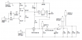
Hi, the following is a Buck-Boost circuit which I am trying to build.


The problem is that I am not receiving any output from the IR2117 so the rest of the circuit is not working.
I am supplying a Vcc of 16V and no current is being drawn from the supply.
From the PWM Module there is a transistor stage as to drive the IR2117 at 15V for high.

In reality C5 is 6.84nF however I approximated it to 1uF.

Any idea what the problem might be?

Thanks
 

Attachments

Thread Starter

lukegalea16

Joined Apr 8, 2017
3
Hi, thank you for your reply.

If I am not mistaken that is because we used a PNP transistor due to the inversion of the signal when operated as a switch. In any case my group had tested the output of that stage before connecting to the IR2117 and the oscilloscope clearly showed a 15V peak so that part should be good.
 

AlbertHall

Joined Jun 4, 2014
12,619
Is R7 really 14.3Ω?
With Q2 the right way round that would give about 1A collector current in Q3 and 1A base current in Q2 :eek:
 

Alec_t

Joined Sep 17, 2013
15,101
You may well have Q2 the right way round in the built circuit, but it is shown with the collector and emitter wrongly connected in the schematic.
What is the purpose of D4 (a 60V zener diode) if your supply is 16V?
Q2 and Q3 are unlikely to survive the 1A current Albert pointed out.
 

crutschow

Joined Mar 14, 2008
38,316
If I am not mistaken that is because we used a PNP transistor due to the inversion of the signal when operated as a switch. In any case my group had tested the output of that stage before connecting to the IR2117 and the oscilloscope clearly showed a 15V peak so that part should be good.
But you are mistaken. ;)
A pnp requires the collector voltage be more negative than the emitter.
You circuit has it opposite, and it won't work well as a transistor as shown.
It will still have a signal output because transistors will work in the inverted state, although with very low current gain.

The Ltspice simulation below (assuming R7 on your schematic is 14.3k) shows the difference between the incorrect transistor connection output (Vout1) and the correct connection (Vout2).
I assumed D4 on your schematic is a Schottky to prevent transistor saturation, so I made a substitution there also.

upload_2017-4-8_11-48-20.png

So, if you are getting a full 15V output from Q2's load resistor R9 (in your schematic) then the transistor is likely connected correctly with the emitter going to V1.
 

WBahn

Joined Mar 31, 2012
32,703
In any case my group had tested the output of that stage before connecting to the IR2117 and the oscilloscope clearly showed a 15V peak so that part should be good.
Is this some kind of homework/school related project? If so, you will probably get better feedback (i.e., feedback that is focused on helping you learn instead of just getting the circuit to work) if we move it to the Homework Help forum.
 

Thread Starter

lukegalea16

Joined Apr 8, 2017
3
Hi, thank you all very much for your help.
I really do appreciate it.

Yes it is a school related project in fact I still have to discuss the circuit with my lecturer.

Thanks
 
Top