 Facebook
 Google
 GitHub
 Linkedin
Hi,
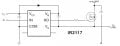
I have simulated the attached circuit without anything connected to HO output. I have a 5V square wave going into IN and a 10V square wave coming out of HO.
Now I have set the same circuit up on a breadboard and done the same thing but I have a 20V constant voltage coming out of HO.
Not sure why this is the case. Does anyone know what could be the problem here?
Attachments
-
 39.1 KB Views: 43


