 Facebook
 Google
 GitHub
 Linkedin
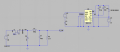
I'm trying to design a buck converter (not synchronous). I use IR2110 (high side) to control the mosfet. As I know that pin VS need to connect to GND so the bootstrap capacitor can be charged. But by that way, accidentaly, in buck conveter, 2 side of the diode are short-circuit.
If I use another source for IR2110 and separate 2 GND then It's not able to send the PWM to HIN pin.
I'm confused about that. Could anyone please help me!
If I use another source for IR2110 and separate 2 GND then It's not able to send the PWM to HIN pin.
I'm confused about that. Could anyone please help me!
Attachments
-
 309 KB Views: 72
")


