Facebook
 Google
 GitHub
 Linkedin
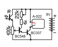
3x NPN 1xPNP 6x resistorswith the actual inventory?
voltage follower and the other as Schmitt trigger.
") 3-4 resistors for schmitt 3-2 for follower
3-4 resistors for schmitt 3-2 for follower________________________________
¯¯¯¯¯¯¯¯¯¯¯¯¯¯¯¯¯¯¯¯¯¯¯¯¯¯¯¯¯¯¯¯¯¯
((What it's worth . . .)) -- no warranty - whatsoever it'll actually work /!\ -- depends on transistors ir-Sensor and adjustability by 100k pot , and that the components won't get blown while adjusting the grid to operation /!\
 . . . it also may be considered using the 100k pot + photo-diode to bypass the motor and locking the power switch - giving it some 90µA standby + finding a capacitor set up a triggered timer control. . . i'm not into figuring that one out now . . . be better than me !
________________________________
¯¯¯¯¯¯¯¯¯¯¯¯¯¯¯¯¯¯¯¯¯¯¯¯¯¯¯¯¯¯¯¯¯¯
. . . usually if you don't do it now - you'll never do it
here we go
________________________________
¯¯¯¯¯¯¯¯¯¯¯¯¯¯¯¯¯¯¯¯¯¯¯¯¯¯¯¯¯¯¯¯¯¯
Both of the above circuits have question marks as :
• if the motor already is not self timed to run the round loding cycle then you have to time the iR source on 1-st example
• in the second example the delay depends on env. temperature and battery condition
(for 9V 6F22 the loading cycles for 1-st 5 rounds may occur normally but then the battery "exhausts" and following may fail -- if the weather is warm - above 20°C(68°F) - the internal chemistry recovers the battery charge in 30 minutes to several hours)
shortly you may need a more complex control circuit for any practical and reliable operation
Attachments
-
3.4 KB Views: 5
-
3.6 KB Views: 3
Last edited: