The PNP, NPN and IR LED are turned on during each burst of 30kHz each time the TLC555 output goes low, or they are turned off during each gap and when the TLC555 output goes high at 30kHz.
I also do not have a program to do schematics. Instead I copy parts from other schematics and datasheets then paste them into Microsoft Paint program.
Did you open and understand my attachment?
I see that you aded a voltage divider on the colector of PNP.I am not sure why?? Is this due maintaining 1.65 V on the base of NPN (2200/2200+100+390)×2 V=1.65?
I see that you aded a voltage divider on the colector of PNP.I am not sure why?? Is this due maintaining 1.65 V on the base of NPN (2200/2200+100+390)×2 V=1.65?
The 2.2k resistor turns off the PNP transistor quickly, it barely affects the base current in the NPN.
The 100 ohm resistor has 20mA in it and the 2.2k resistor has 0.7V/2.2k= 0.3mA in it so the base current to the NPN is 19.7mA instead of 20mA. The base-emitter of a transistor sets its own voltage at about 0.7V.
So i will attach my schematic.
Sory about drawing, i know it is little messy...
Notice: my desired current is 140 mA since IR led forward current is 150 mA
Is there any possibility to connect inductor/coil for increasing life span of a battery?
I forgot that you are using two TLC555 oscillators like Bernard had. That is why Bernard said that when the second TLC555 is reset then its output is low, that would have turned on the IR LED and waste battery power before. So I changed the transistors circuit so that the IR LED is turned off during the reset gaps in the pulses.
Your IR detector will light its LED when the IR beam is not blocked by a burglar.
Two name-brand AA alkaline cells will last for only 12 hours but operate the IR transmitter poorly for the last 8 hours.
Beware, some alkaline D cells have a little AA or C cell inside.
Very nice!!!Thank you Agu!
Since i am planing to use 2 TLC's as switch to turn on and off TSOP it would operate maybe 1 minute in a day.Something like TV remote.It would not be on for whole time.I just need to find out a way that when i press switch one time, TSOP circuit will be on and a second switch push TSOP circuit will be off(remote).TSOP circuit(maybe a light bulb or something) would operate on 9 V batery.
When you want to operate a 555 at less than 50% duty cycle, a diode can be connected between pins 6 & 7, anode to pin 7. Refer to page 6, post # 107, U1. On time depends on C1 charging time. C1 X R1, R2 is bypassed by D1. Discharge time R2 X C1, Total pulse period is the sum of charge time & discharge times. Operating both ICs at 30% will save battery current.
Your schematic looks good, numbers & letters need work.
Thank you...i tried conecting a diode and i get a d.c. of about 7%.But diode is another element that requires voltage drop of about .7 V that is not desirable for the batery life.My drawing is by hand thats why is a bit messy.
I have few questions about schematic that posted audioguru
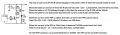
1.This labeled in red,can this be qualified as a voltage divider?
2.How large is voltage at point A?
3.How these two resistors impact on PNP and NPN?
4.How large is the current running from 3V rail through 2200 ohm resistor?
5.How large is the current through 120 ohm resistor?
Can someone explain me a little bit more?
Thank you
No. The 2.2k resistor is used to quickly turn off the PNP transistor. When the PNP transistor is turned on it has a base current of about 15mA but the current in the 2.2k resistor is only 0.8V/2.2k= 0.4mA so the base gets almost all the current.
Point A is the base of the PNP transistor. It is at the positive supply voltage when the transistors are turned off and it is the normal turned-on base-emitter voltage of a little turned-on transistor that has a 150mA collector and a 15mA base currents. The turned-on base-emitter voltage is about 0.8V as shown on the datasheet of almost every little transistor.
Without the 2.2k resistor then the PNP transistor might turn off so slowly that it cannot produce 30kHz.
Without the 120 ohm resistor calculated to limit its current to about 15mA then the base of the PNP transistor might burn out.
4.How large is the current running from 3V rail through 2200 ohm resistor?
Again use Ohm's Law: (3V - 0.2V - 0.8V)/120 ohms= 16.7mA. If a 133 ohms resistor was available then the current would be (3V - 0.2V - 0.8V)/133 ohms= 15mA.
No. The 2.2k resistor is used to quickly turn off the PNP transistor. When the PNP transistor is turned on it has a base current of about 15mA but the current in the 2.2k resistor is only 0.8V/2.2k= 0.4mA so the base gets almost all the current.
Point A is the base of the PNP transistor. It is at the positive supply voltage when the transistors are turned off and it is the normal turned-on base-emitter voltage of a little turned-on transistor that has a 150mA collector and a 15mA base currents. The turned-on base-emitter voltage is about 0.8V as shown on the datasheet of almost every little transistor.
Without the 2.2k resistor then the PNP transistor might turn off so slowly that it cannot produce 30kHz.
Without the 120 ohm resistor calculated to limit its current to about 15mA then the base of the PNP transistor might burn out.
Use Ohm's Law: 0.8V/2.2k= 0.4mA.
{quote]5.How large is the current through 120 ohm resistor?
Again use Ohm's Law: (3V - 0.2V - 0.8V)/120 ohms= 16.7mA. If a 133 ohms resistor was available then the current would be (3V - 0.2V - 0.8V)/133 ohms= 15mA.
[/QUOTE]
Thank you agu.As always you helped me alot.
 Facebook
 Google
 GitHub
 Linkedin