 Facebook
 Google
 GitHub
 Linkedin
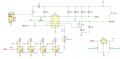
I'm new to circuit design. I'm using an Injoinic IP5306 battery charging IC (datasheet). I also use an AMS1117-3.3 (datasheet) to drop down the 5V power it produces to 3.3V. I've attached a picture of my schematic which shows the relevant portions, the IP5306 in single-LED configuration, the AMS1117-3.3 circuit, and the 4 WS2812B LEDs (datasheet) that I'm trying to drive. The batter terminals connect to a Li-ion 18650 battery.
## Problem Description
When running on battery power, this circuit works for about 33 seconds and then "fails and shuts off". When running on 5V USB power it runs forever, and also correctly charges the battery. I state it "works" because I can program the test pattern which drives the LEDs as expected. When it "fails and shuts off" it shows this soft blinking red pattern.
Here's a video showing the problem:
Voltage measurements of the AMS1117-3.3 pins show: The 5V input is fluctuating between 1.55 - 1.67 V which is creating the red blinking effect for the LEDs. The AMS1117 pin for 3.3V output is fluctuating between 0.72 and 0.82. I have a few independant hardware devices so I think it's safe to say this is a design issue. The power at the battery when it's supplying power is ~ 4.0 V.
## Questions
What is the flow the unexpected power is taking in my circuit?
Why does it was 33 seconds to power off?
What tools and techniques do I need to learn to analyze these types of failures?
Do you see a problem with my schematic?
Thank you!
Brian
Attachments
-
 38.7 KB Views: 105


