
Inverted LED bar temperature graph for Dynamic Redline indicator - LM3914/15/16(?)

Audioguru again

Joined Oct 21, 2019
6,826
Some LM339 or LM2901 ICs produce an output current of 20mA but their minimum output current is only 6mA and with a saturation voltage loss of 1.5V. You might be unlucky and get unmatched LM339 outputs or both are weak ones.
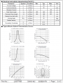
I could not find the brightness spec's for the L200TR5B red LED.
 

eetech00

Joined Jun 8, 2013
4,711
Some LM339 or LM2901 ICs produce an output current of 20mA but their minimum output current is only 6mA and with a saturation voltage loss of 1.5V. You might be unlucky and get unmatched LM339 outputs or both are weak ones.
I could not find the brightness spec's for the L200TR5B red LED.
HI

I just used that LED as a demo.
But here is the spec.

1575565011973.png
 

Bernard

Joined Aug 7, 2008
5,784
For V reg. 6V to 10 V @ 250 mA minimum. I still would use 10 mA for LEDs . You will see little difference
between 10 mA & 20 mA, but with 20 ma should use drivers.
Schematic by @eetech00 drops R18- R25 a good thing but I would aim for 10k - 100k, 10 to 20 turn pots.
LM2901NEA should be a DIP.
 

Thread Starter

Juliuswws

Joined Dec 2, 2019
20
Sorry guys, it was just my brainfart about the 20mA for the LEDs. I haven't chose them yet and I thought some might draw more current, but in reality, it'll draw as much as I allow with the resistors.
So I guess its safe to say that the complete circuit will not draw more than 1A @ 9V.
I'll do the shopping tomorrow.

eT: Sorry, I meant the schematic diagram in a format which I could open with some circuit designer/ PCB design software to get a sensible layout.

Thanks for everyone for all the replies!
 

Thread Starter

Juliuswws

Joined Dec 2, 2019
20
An accident is just one inattentive (other) driver away. I got t-boned by one such girl and it changed my life.
Sorry to hear that mate!
I know indeed its not only up to me. I drive in a defensive way, thats the most I can do.
Cheers
 

eetech00

Joined Jun 8, 2013
4,711
Sorry guys, it was just my brainfart about the 20mA for the LEDs. I haven't chose them yet and I thought some might draw more current, but in reality, it'll draw as much as I allow with the resistors.
So I guess its safe to say that the complete circuit will not draw more than 1A @ 9V.
I'll do the shopping tomorrow.
You can probably use 500mA@9V if you want.

eT: Sorry, I meant the schematic diagram in a format which I could open with some circuit designer/ PCB design software to get a sensible layout.

Thanks for everyone for all the replies!
I recommend you re-create the schematic in the design software of your choice. Believe me, that will be much easier than trying to translate/transfer the netlist into the target design software.

eT
 

dl324

Joined Mar 30, 2015
18,432
I drive in a defensive way, thats the most I can do.
Nothing can protect you from someone who doesn't "obey a traffic control device". I was on a state highway where the speed limit was 50MPH and had the right of way (no stop sign). She was on a cross street with a 35MPH limit and a stop sign. She didn't stop.

At least I didn't roll the vehicle, but it was close. She hit us hard enough to turn us 180 degrees. I fought like he** with a dead engine and no power steering to stay out of the ditch that would have likely made us roll and cause more severe injuries.
 

Audioguru again

Joined Oct 21, 2019
6,826
The datasheet for an LM339 or LM2901 shows 6mA outputs if you get a passing but weak one. Also the weak ones have a saturation voltage loss of 1.5V when the output is only 6mA. If you use two ICs then their maximum output currents probably will not match causing different LED brightnesses.
 

eetech00

Joined Jun 8, 2013
4,711
Hello

what audio guru again is implying is that the comparator output current can be as low as 6mA and still be in spec. So if your minimum LED current requirement is 10 mA, you will need an external drive transistor connected to each comparator output to drive the LED.

eT
 

eetech00

Joined Jun 8, 2013
4,711
For V reg. 6V to 10 V @ 250 mA minimum. I still would use 10 mA for LEDs . You will see little difference
between 10 mA & 20 mA, but with 20 ma should use drivers.
Schematic by @eetech00 drops R18- R25 a good thing but I would aim for 10k - 100k, 10 to 20 turn pots.
LM2901NEA should be a DIP.
Hi

1. Can we use an LM311 instead of LM339 so to get higher output current (40mA max)?
2. The Temperature sensor is shared with an MCU input. Add Opamp Buffer?

eT
 
Last edited:

MisterBill2

Joined Jan 23, 2018
27,824
Several things matter here. First, at least one of those LED bar graph ICs is divided in decibles, not a linear arrangement. So you need to determine which one you need.
Now for using the present temperature sensor, you need to measure the voltage on the terminal at the temperatures that you are interested in. If it is a one-terminal device then the engine block ground is the second connection, but if it is a 2 terminal device it will be more complicated. To drive your bar graph in the reverse direction you may need to use an inverting op-amp circuit, or you may be able to use two quad comparator ICs and bias their opposite inputs to provide just the function that you want. The LM339 has 4 open collector comparators that could easily drive one LED each. So the circuit is easy and simple, but first you need to know what your temperature sensor voltage does as the engine heats up. Rather that try to analyze the present circuit just measure the voltages at temperatures, and then let us know. The comparators will operate either in the inverting mode or the non-inverting mode, depending on which way the voltage goes.
And if you use "High brightness" LEDs they will be quite bright enough when driven by an LM339.
 

eetech00

Joined Jun 8, 2013
4,711
Several things matter here. First, at least one of those LED bar graph ICs is divided in decibles, not a linear arrangement. So you need to determine which one you need.
Now for using the present temperature sensor, you need to measure the voltage on the terminal at the temperatures that you are interested in. If it is a one-terminal device then the engine block ground is the second connection, but if it is a 2 terminal device it will be more complicated. To drive your bar graph in the reverse direction you may need to use an inverting op-amp circuit, or you may be able to use two quad comparator ICs and bias their opposite inputs to provide just the function that you want. The LM339 has 4 open collector comparators that could easily drive one LED each. So the circuit is easy and simple, but first you need to know what your temperature sensor voltage does as the engine heats up. Rather that try to analyze the present circuit just measure the voltages at temperatures, and then let us know. The comparators will operate either in the inverting mode or the non-inverting mode, depending on which way the voltage goes.
And if you use "High brightness" LEDs they will be quite bright enough when driven by an LM339.
Hi

The sensor is a two terminal device (implying three connections) and it will be shared with an input to an MCU inside a stepper motor gauge. The idea is to use a custom level detector (Bernard's circuit) to drive the LEDs instead of a bargraph IC. The TS want the LEDs lit in up or down sequence either all on or all off (Bar mode).

eT
 

MisterBill2

Joined Jan 23, 2018
27,824
Hi

The sensor is a two terminal device (implying three connections) and it will be shared with an input to an MCU inside a stepper motor gauge. The idea is to use a custom level detector (Bernard's circuit) to drive the LEDs instead of a bargraph IC. The TS want the LEDs lit in up or down sequence either all on or all off (Bar mode).

eT
In some automotive applications the two terminals serve two different functions. But perhaps the TS has already measured the device and knows more than was stated in the initial posting. THAT happens many times here. And none of that matters if a low impedance system is monitored by an isolated high impedance system, which I think is what the TS is asking for. If you do connect another measurement package to that same sensor then you will need an isolated power source or an isolated input arrangement.
 
Last edited:

MisterBill2

Joined Jan 23, 2018
27,824
If you use the LM339 comparator and the brightness is not enough you can use a CD4049 or CD4050 as LED drivers and level shifters, because they can sink more current, and they don't take much input current.

But my experience as well as the information from engineers in the engine business is that the engine is ready for producing major power just a few seconds after starting up, if it is not a diesel engine. So I let it warm up while I fasten my seat belt. The pressure comes up and I am all set by then. Full warmup time will depend on the outside temperature, and so in some parts of the world it may take more or less time.
 

eetech00

Joined Jun 8, 2013
4,711
Hello,

I think the remaining issue is not how to create the bargraph circuit, but how to share the same temperature sensor between the gauge MCU and the bargraph circuit. Or if that's even practical for this application.

I believe the sensor is passive and is energized by either the MCU or engine battery. Perhaps the TS can measure the voltage at the sensor while its operating so we can determine if/how to condition it.

eT
 

Bernard

Joined Aug 7, 2008
5,784
With +9V, R9 = 2k, a plot of V & temp shows a linear plot from 85 to 60 deg. & 60 to 40 deg.
LM3914 still tempting? Real measurements might show something different.
 

MisterBill2

Joined Jan 23, 2018
27,824
All that is required is an adequately high enough impedance input on the second circuit, and an op-amp with a common mode voltage tolerance adequate to handle whatever common mode voltage exists on that temperature sensor. That could be what is called an "instrument amplifier", which is designed for exactly that purpose. Those ICs are made by Analog Devices company among others.
 
Top





