Inverted LED bar temperature graph for Dynamic Redline indicator - LM3914/15/16(?)

Reloadron

Joined Jan 15, 2015
7,893
Thank you for all the replies!

I'm not too sure how could I use the working principle of a VU meter as the circuit should be controlled by varying resistance rather than voltage. Also, I need this to be work inverted, so all LEDs ON by default.

Unfortunately, there is no part number for the NTC. All I know is 3 values for 3 temperature values.
104F (40C) = 925 ohms
194F (90C) = 163 ohms
302F (150C) = 32 ohms
This seems logaritmic to me.

The sensor: http://prosportgauges.com/temperature-sender.aspx

The gauge is stepper motor driven, thats all I know about it, but I wouldn't like to open it to extract some signal from it.

The gauge I have: https://rspec.co.uk/gauges-52mm-pro...-super-white-oil-pressure-gauge-bar-p-80.html

Dodgydave: So the LM3914 could be configured with pin 4 and 6 to have all outputs ON by default and they would go out one by one as the resistance drops (within set values) on pin 5?

Thanks again
That seems logarithmic to me also. The problem is the LM3914 is linear in its response. My guess is your sensor is a thermistor and as mentioned has a negative temperature coefficient. You can use the LM3914 and it will be accurate at the top and bottom but not in between. Long as you can live with that the LM3914 will do fine.

Ron


Thread Starter

Juliuswws

Joined Dec 2, 2019
20
That seems logarithmic to me also. The problem is the LM3914 is linear in its response. My guess is your sensor is a thermistor and as mentioned has a negative temperature coefficient. You can use the LM3914 and it will be accurate at the top and bottom but not in between. Long as you can live with that the LM3914 will do fine.

Ron


Thanks for your reply

As I was reading about these ICs, I found LM3915 which supposed to be a logaritmic output type. Would that be more accurate?
Also, could I simply connect the thermistor to the signal input of the LM39XX or I would need an opamp or something?

Cheers
 

Dodgydave

Joined Jun 22, 2012
11,395
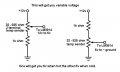
Ideally measure the voltage across the ntc sensor, chances are one end will go to chassis, otherwise it will go to positive to see how it's wired..if it goes to chassis then the voltage will decrease as the temperature increases...
 

Reloadron

Joined Jan 15, 2015
7,893
Thanks for your reply

As I was reading about these ICs, I found LM3915 which supposed to be a logarithmic output type. Would that be more accurate?
Also, could I simply connect the thermistor to the signal input of the LM39XX or I would need an opamp or something?

Cheers
Yes, the LM3915 provides a bar or dot display mode externally selectable logarithmic 3 dB/step analog display. So what you have is a 30 db range and yes, it is logarithmic. Their popular use was generally for LED display VU Meters in audio applications. I just don't see a 3915 working out for you.
Looking at the resistances for your sensor they are sort of unusual in that I can't get those numbers to correlate to any common thermistor charts. Yet, the sensor was obviously designed to work with a display or system of some sort.

When using thermistors with for example micro-controllers the Steinhart-Hart equation is generally used to get a square law response. Problem is I don't know how to get the steps of a LM3914 or LM3915 to accurately read a thermistor.

Ron
 

Audioguru again

Joined Oct 21, 2019
6,826
Fake ICs from China sell well when Western parts become obsolete. I bought an LM3915 from a local electronics parts liquidator (Sayal) from India. It works but it looked like it was used, not new.
 

Thread Starter

Juliuswws

Joined Dec 2, 2019
20
Thanks for all the replies again

Seeing the different answers, looks like everyone has different opinions if it can be achived with LM3914/15.
Still, I ordered some 3915s from aliexpress (5pcs for a 1$) for experimental purposes. I will get the rest from a proper online shop (Farnell - Ireland)

Maybe this LM3914/15 approach is wrong...I cant figure it out yet.
Could this be built with individual transistors to drive the LEDs one by one?

I worked out the resitor values vs temperature from the sensors:
40C = 925
45C = 780
50C = 650
55C = 545
60C = 460
65C = 380
70C = 325
75C = 270
80C = 225
85C = 190 Ohms

To recap: All LEDs should be OFF below 190 Ohms, all ON at and above 925 Ohms

I have NI Multisim (V.13.0) installed, but not entirely sure yet how to properly use it and it has no LM39XX in its database.

Thanks
 

eetech00

Joined Jun 8, 2013
4,709
Yes, the LM3915 provides a bar or dot display mode externally selectable logarithmic 3 dB/step analog display. So what you have is a 30 db range and yes, it is logarithmic. Their popular use was generally for LED display VU Meters in audio applications. I just don't see a 3915 working out for you.
Looking at the resistances for your sensor they are sort of unusual in that I can't get those numbers to correlate to any common thermistor charts. Yet, the sensor was obviously designed to work with a display or system of some sort.

When using thermistors with for example micro-controllers the Steinhart-Hart equation is generally used to get a square law response. Problem is I don't know how to get the steps of a LM3914 or LM3915 to accurately read a thermistor.

Ron
hi Ron

I think it’s fairly easy to linearize a thermistor. then just use a 3914. But If the same sensor is shared by the gauge and Bargraph, how to interface the bargraph without affecting the signal to/from the MCU in the gauge.

eT
 

Dodgydave

Joined Jun 22, 2012
11,395
Thanks for all the replies again

Seeing the different answers, looks like everyone has different opinions if it can be achived with LM3914/15.
Still, I ordered some 3915s from aliexpress (5pcs for a 1$) for experimental purposes. I will get the rest from a proper online shop (Farnell - Ireland)

Maybe this LM3914/15 approach is wrong...I cant figure it out yet.
Could this be built with individual transistors to drive the LEDs one by one?

I worked out the resitor values vs temperature from the sensors:
40C = 925
45C = 780
50C = 650
55C = 545
60C = 460
65C = 380
70C = 325
75C = 270
80C = 225
85C = 190 Ohms

To recap: All LEDs should be OFF below 190 Ohms, all ON at and above 925 Ohms

I have NI Multisim (V.13.0) installed, but not entirely sure yet how to properly use it and it has no LM39XX in its database.

Thanks

As you are aware the Thermistor is Not Linear, so the Voltage swing will be greater as it cools down, if the thermistor is wired to ground like in post#24, then as it cools down the voltage will rise and all leds will be on, and as it heats up all leds will go out one by one, this can be inverted using an op amp, or buffered and the gain altered to suit the thermistor to make it slightly linear..
 

Bernard

Joined Aug 7, 2008
5,784
Then you could make your own log bar readout. 10 comparators with all neg. inputs common to V divider as in post #24, 1k & sensor to + 12 V ( regulated ),
pos. inputs to individual dividers, 1k & 925 down to 1k & 190. Comp. outputs to LED, R to + 12V. Cold all LEDs on, hot, all off.
 

eetech00

Joined Jun 8, 2013
4,709
Thanks for all the replies again

Seeing the different answers, looks like everyone has different opinions if it can be achived with LM3914/15.
Still, I ordered some 3915s from aliexpress (5pcs for a 1$) for experimental purposes. I will get the rest from a proper online shop (Farnell - Ireland)

Maybe this LM3914/15 approach is wrong...I cant figure it out yet.
Could this be built with individual transistors to drive the LEDs one by one?

I worked out the resitor values vs temperature from the sensors:
40C = 925
45C = 780
50C = 650
55C = 545
60C = 460
65C = 380
70C = 325
75C = 270
80C = 225
85C = 190 Ohms

To recap: All LEDs should be OFF below 190 Ohms, all ON at and above 925 Ohms

I have NI Multisim (V.13.0) installed, but not entirely sure yet how to properly use it and it has no LM39XX in its database.

Thanks
Hi

1. How did you obtain those values?

2. Can you get a reading at 25C?

3. Some gauges might provide "breakout pins" that will allow the unit to interface to other devices. Does yours?

eT
 

Thread Starter

Juliuswws

Joined Dec 2, 2019
20
Hi

1. How did you obtain those values?

2. Can you get a reading at 25C?

3. Some gauges might provide "breakout pins" that will allow the unit to interface to other devices. Does yours?

eT
Hi,

I just threw the existing 3 values into a graph, made the resistance axis logaritmic and temp axis linear which resulted a straight line. Which makes me think this is a logarithmic sensor. Than I just read the data from the graph.

I haven't purchased a second sensor yet,I want to make sure a simple circuit can be created around it. I'm currenly unable to test the currently installed sensor

This gauge has no breakout pins unfortunately to chain it with another one

Cheers
 

Thread Starter

Juliuswws

Joined Dec 2, 2019
20
Then you could make your own log bar readout. 10 comparators with all neg. inputs common to V divider as in post #24, 1k & sensor to + 12 V ( regulated ),
pos. inputs to individual dividers, 1k & 925 down to 1k & 190. Comp. outputs to LED, R to + 12V. Cold all LEDs on, hot, all off.
Thank you! This sounds good, however I only understand maybe the half of it. All I know from this that I'll need a low dropout voltage regulator to create 12V from the cars 12.8V - 14V, the rest is cloudy.
Any chance someone could throw together a quick schematic diagram? (And if an auto routed PCB layout is only a few clicks away in some software, that as well)
Thank you
 

Bernard

Joined Aug 7, 2008
5,784
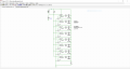
Here is my version of 8 stage bar graph. LM339 has 4 stages but more can be added. R10-R17 can be multi turn 1k to 10k pots, Around US $ .25 to $ 2. Series R same as pot. , or one R of 1/10 value & common to all stages.
Say a 2k pot.; individual R 1k8-( 1.8k ). With + sides of all pots tied together the one R would be 200. With red LEDs, R1 = 680 for about 10 mA.
 

Attachments

Thread Starter

Juliuswws

Joined Dec 2, 2019
20
Bernard, eT, this looks awesome, thank you!
Still got a few questions:

Voltage regulator: Would a 1A do the job fine with or without heatsink?
Didn't choose the LEDs yet but I guess they will draw about 20mA each, TI LM339AN...well it says 2mA max supply current with no load, I couldn't find absolute maximum + the rest of the passives.
All and all, I don't need exact calculation, just an opinion if a 9V/1A device will do the job or I need 1.5A

Quad Differential Comparator: Being my first ever circuit build, I want to go through hole using perfboard.
I found few chips in DIP package with different letters at the end (AN, N, NG). Does this matters much to this application?
I think they just indicate response time and min-max supply voltages.

Pots: R10 to R17 will be the pots to adjust when each LED will turn off. I can go multiturn ones. Just want to make sure the range suggested by yourselves ( 1K to 10K) is correct. Just asking because the sensor will work in the sub K range.

eT: If not too much to ask, could you send the circuit in some file format? I will try to stick it into Multisim/Ultiboard to create some sort of sensible PCB layout. I started replicating your drawing in Multisim, but it'll take me one day :)

Thanks again guys!
 

eetech00

Joined Jun 8, 2013
4,709
Bernard, eT, this looks awesome, thank you!
Still got a few questions:

Voltage regulator: Would a 1A do the job fine with or without heatsink?
Didn't choose the LEDs yet but I guess they will draw about 20mA each, TI LM339AN...well it says 2mA max supply current with no load, I couldn't find absolute maximum + the rest of the passives.
All and all, I don't need exact calculation, just an opinion if a 9V/1A device will do the job or I need 1.5A

Quad Differential Comparator: Being my first ever circuit build, I want to go through hole using perfboard.
I found few chips in DIP package with different letters at the end (AN, N, NG). Does this matters much to this application?
I think they just indicate response time and min-max supply voltages.

Pots: R10 to R17 will be the pots to adjust when each LED will turn off. I can go multiturn ones. Just want to make sure the range suggested by yourselves ( 1K to 10K) is correct. Just asking because the sensor will work in the sub K range.

eT: If not too much to ask, could you send the circuit in some file format? I will try to stick it into Multisim/Ultiboard to create some sort of sensible PCB layout. I started replicating your drawing in Multisim, but it'll take me one day :)

Thanks again guys!
Hi

We'll wait to hear from Bernard, but...

Comparator-
You'll probably need the automotive grade version of the LM339 chip, LM2901-Q1
The max output is 20ma, so if you need more current output then 75%, an external drive transistor for each will be needed.
I would use DIP packages because they are easier to work with on perfboard or PCB. SMD devices are better for Mass production.

File format-
If using windows, double click the image, then right click over the image, you can save it as a picture file.
Be aware, there will probably be corrections to the schematic.

eT
 
Top