Facebook
 Google
 GitHub
 Linkedin
allan.w.macdonald
- Joined Nov 3, 2010
- 8
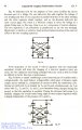
I took them to be a simple representation of a capacitor !
If it is just an artists rendering as suspected then the interpretation is moot!
All in the eye of the beholder
In your schematic, I can't tell if L3 coupled to the the coupled inductor (transformer) L1/L2? The extra lines in the book cover suggest this but I'm not sure.